
Calibration device and calibration method used for indoor pyranometer
A technology of total solar radiation and calibration devices, which is applied in measuring devices, photometry, optical radiation measurement, etc., can solve the problems of calibration work limitations, affecting calibration work progress and stability, and achieve short calibration time and high data quality. Strong reliability and stable light source
Patent Information
- Authority / Receiving Office
- CN · China
- Patent Type
- Applications(China)
- Current Assignee / Owner
- Publication Date
- 2012-06-20
Smart Images
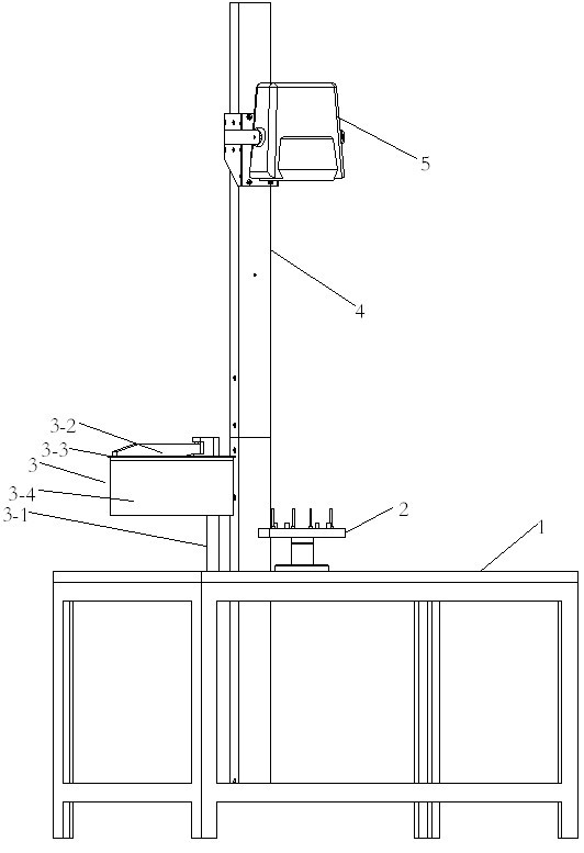
Figure 1 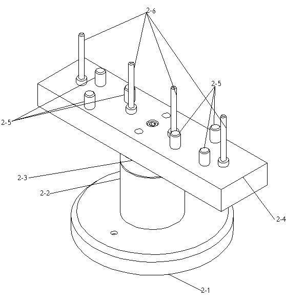
Figure 2 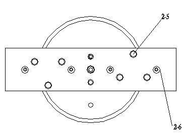
Figure 3
Abstract
Description
technical field
[0001] The invention relates to a calibration device and a calibration method for an indoor pyranometer. The pyranometer is a most-used instrument for measuring solar irradiance in the meteorological field. Background technique
[0002] At present, the calibration of pyranometers in our country is done outdoors and needs to be carried out under clear weather conditions. If the weather is slightly cloudy, the calibration cannot be performed, which seriously affects the progress and stability of the calibration work, and has a great impact on the calibration work. limitations. Contents of the invention
[0003] In view of the deficiencies in the prior art, the present invention provides a calibration device and calibration method for an indoor pyranometer that is not affected by weather changes and can be calibrated at any time.
[0004] In order to achieve the above object, the present invention adopts the technical solution as follows: a calibration ...
Examples
Embodiment Construction
[0021] Such as figure 1 , 2 , shown in 3, a kind of calibration device that is used for indoor pyranometer, comprises workbench 1, rotary platform 2, shader 3, light source support 4, illuminating lamp 5, and rotary platform 2 comprises chassis 2-1, fixed Axis 2-2, rotating shaft 2-3, rotating beam 2-4, supporting column 2-5, positioning column 2-6, rotating beam 2-4 are rectangular bodies, and three The supporting column 2-5 and two positioning columns 2-6, the rotating shaft 2-3 is fixed on the bottom surface of the rotating crossbeam 2-4, and the thin shaft integrated with the rotating shaft 2-3 is placed on the chassis 2-1 as a Among the bearings provided in the shaft core of the integrated fixed shaft 2-2, the rotating shaft 2-3 is movably connected to the two surfaces of the fixed shaft 2-2; the shutter 3 includes a vertical shaft 3-1 of the shutter, a beam 3-2 of the shutter, Shading disk 3-3, shading cover 3-4, a circle of shading cover 3-4 is fixed at the bottom ...