
Three-jaw necking machine synchronizing by rack
A rack and necking technology, applied in mechanical equipment, belts/chains/gears, friction transmission devices, etc., can solve the uniformity effect of necking cup shape, wall thickness and strength, increase the steps and time of the process, The problem of large changes in the center position of the necking mouth, etc., achieves the effect of being beneficial to metal flow, shortening the process time, and improving the uniformity of wall thickness and strength.
Patent Information
- Authority / Receiving Office
- CN · China
- Patent Type
- Patents(China)
- Current Assignee / Owner
- Publication Date
- 2014-03-19
Smart Images
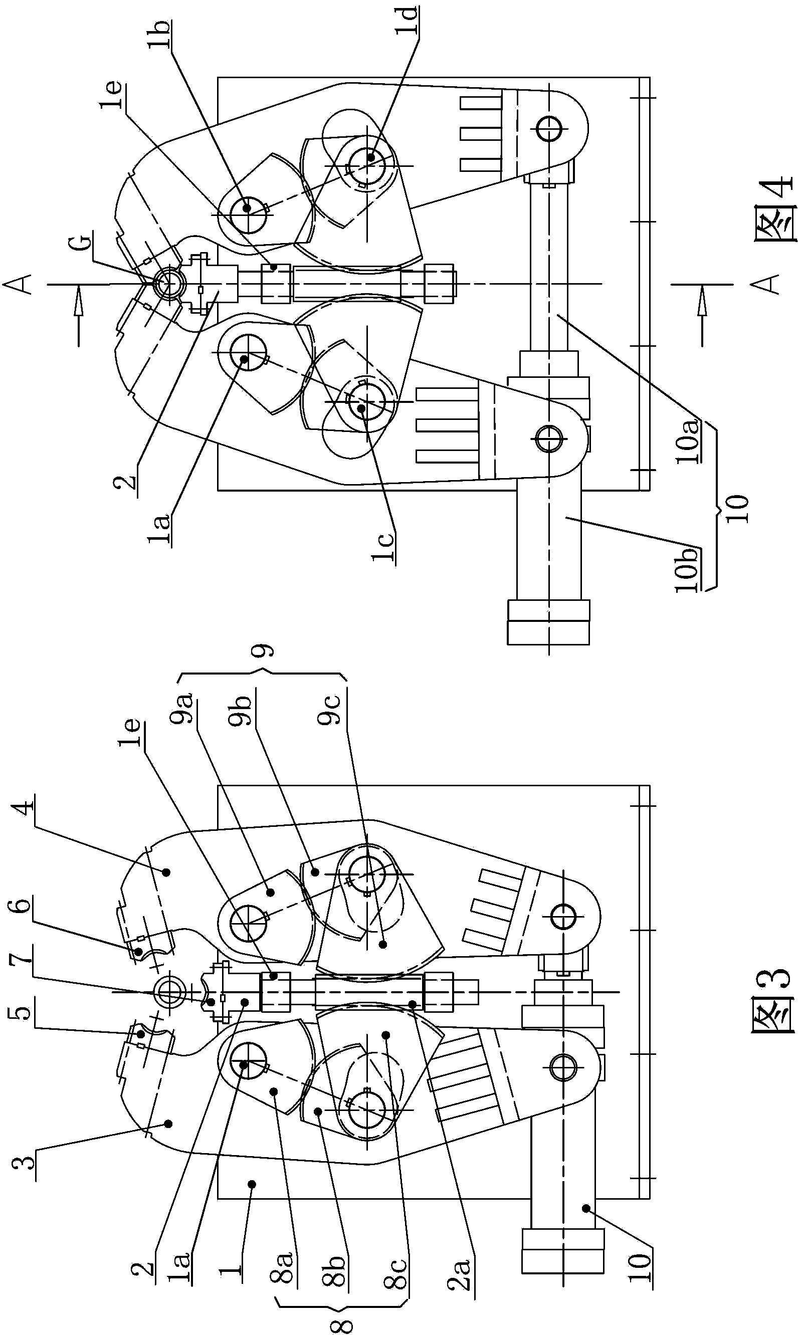
Figure 1 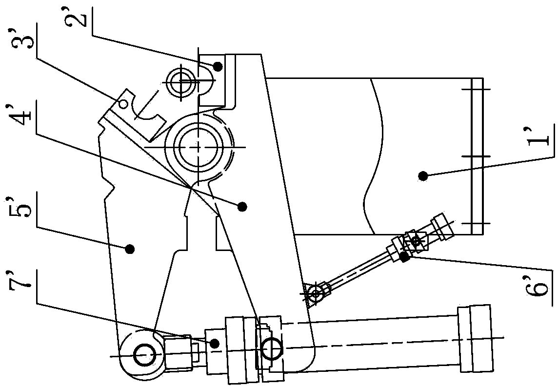
Figure 2 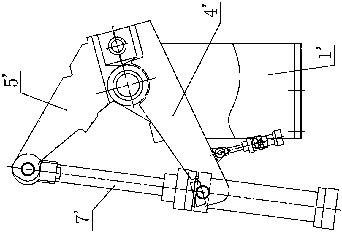
Figure 3
Abstract
Description
technical field
[0001] The invention relates to a three-jaw necking machine in the field of steel pipe production, in particular to a three-jaw necking machine synchronized by racks which can produce seamless steel pipes by adopting a pipe jacking process. Background technique
[0002] At present, there are many methods for the production of hot-rolled seamless steel pipes, such as periodic pipe rolling, automatic pipe rolling, three-roll pipe rolling, two-roll cross rolling, continuous rolling pipe, etc., and the pipe jacking process is also one of them.
[0003] The working principle of the pipe jacking process is to push the ejector rod through the transmission rack, so that the capillary pipe after the pre-piercing mandrel has been shrunk passes through multiple roller dies to extend the pipe jacking and roll out the waste pipe, so as to achieve diameter reduction, wall reduction and extension. Purpose. The steel pipe produced by the pipe jacking process has a series of...
Examples
Embodiment approach 1
[0040] Such as image 3 , 4 and Figure 4A As shown, the embodiment of the present invention proposes a three-jaw necking machine synchronized by racks, which includes a support 1, a telescopic arm 2, first and second rotating arms 3, 4, first, second, and third jaws 5, 6, 7, the first and second gear sets 8, 9 and the executive cylinder 10. The telescopic arm 2 is connected to the support 1 so as to be movable up and down, and a rack with a guide post 2a is arranged under the telescopic arm 2 . The first rotating arm 3 is rotatably connected to the support 1 through the first pin shaft 1a, and the second rotating arm 4 is rotatably connected to the support 1 through the second pin shaft 1b. , The two rotating arms 3 and 4 are located on both sides of the telescopic arm 2 symmetrically. The first, second and third jaws 5, 6 and 7 are respectively connected to the first and second rotating arms 3 and 4 and the telescopic arm 2. The first gear set 8 is connected to the firs...
Embodiment approach 2
[0055] The above-described embodiment is that the execution cylinder 10 is placed horizontally, which directly drives the first and second rotating arms 3 and 4 to rotate, and then through the cooperation relationship between the first and second gear sets 8 and 9 and the rack with guide column 2a, the belt guide Column rack 2a moves. In this embodiment, the actuator cylinder 10 is placed vertically, and it directly drives the movement of the rack with guide pin 2a, and then through the cooperation between the first and second gear sets 8, 9 and the rack with guide pin 2a, the first , two pivoting arms 3,4 rotate. specifically is,
[0056] Such as Figure 7, 8 and Figure 8A As shown, the actuator cylinder 10 has a cylinder rod flat head 10a and a cylinder tube trunnion 10b, the cylinder rod flat head 10a is telescopically connected in the cylinder tube trunnion 10b, and the actuator cylinder 10 is placed vertically, One of the cylinder rod flat head 10a and the cylinder ...