
Chain tool container
A tool and chain technology, applied in the field of automatic tool changing devices, can solve problems such as large number of parts
Patent Information
- Authority / Receiving Office
- CN · China
- Patent Type
- Applications(China)
- Current Assignee / Owner
- Publication Date
- 2014-10-15
Smart Images
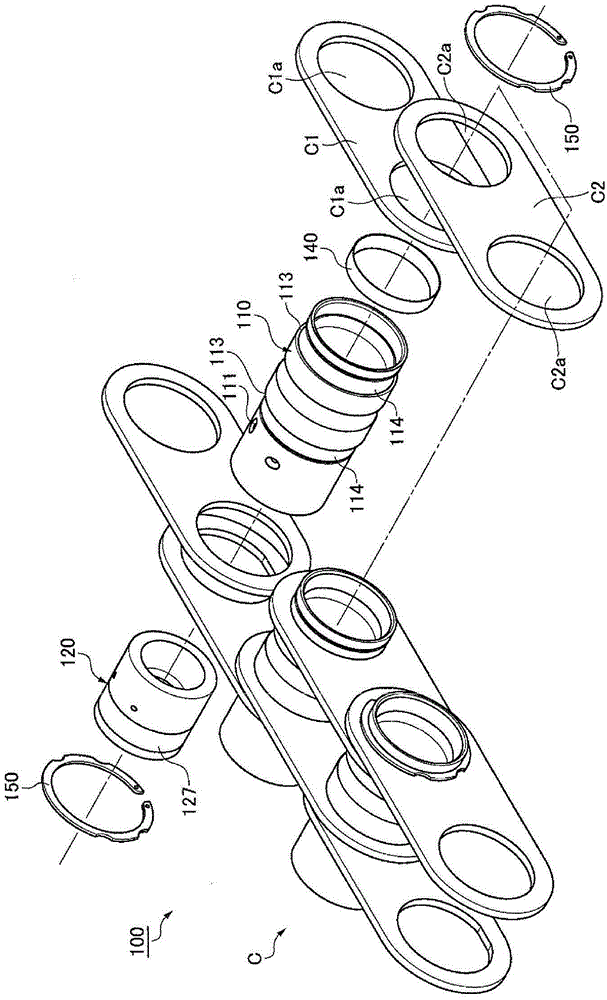
Figure 1 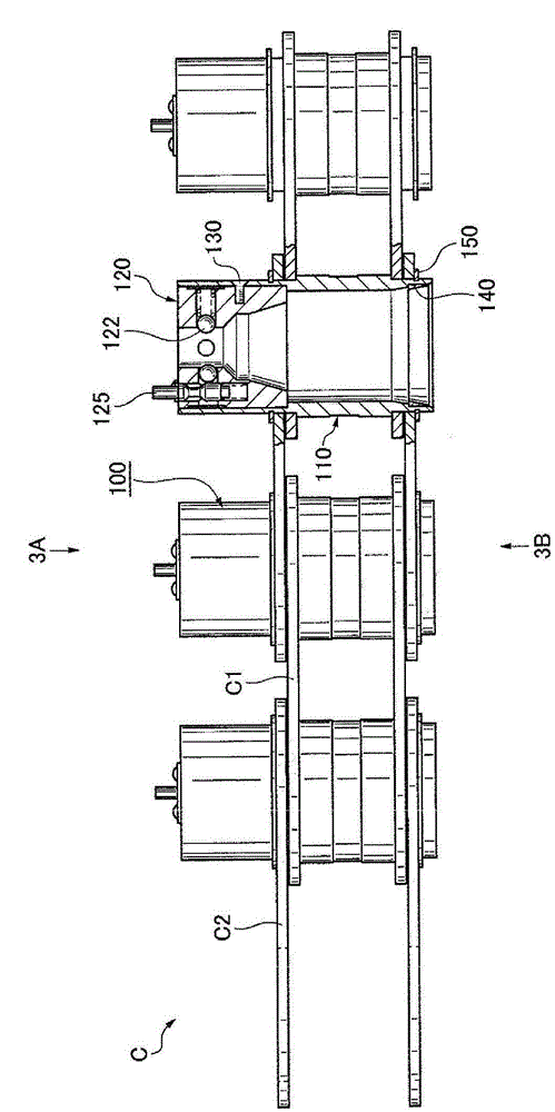
Figure 2 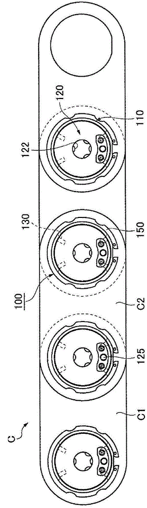
Figure 3
Abstract
Description
technical field
[0001] The present invention relates to a tool pot for a chain used in an automatic tool changer equipped in a machine tool such as a machining center. Background technique
[0002] Conventionally, there is known a tool barrel for chains, which is equipped with a tool holding unit (unit) that holds a tool detachably inside a cylindrical hollow pin (hollow pin). A pair of hollow pins alternately connect a pair of inner plates (plate) and a pair of outer plates (for example, refer to Patent Document 1).
[0003] As such an existing tool box for chains, for example, there are Figure 6(A) to Figure 6(C) Chain tool barrels 700A to 700C are shown.
[0004] Here, FIG. 6(A) is a planar cross-sectional view showing a conventional tool holder 700A for a chain that can freely hold a tool TA of the MAS standard, and FIG. 6(C) is a planar cross-sectional view showing a conventional tool barrel 700C for a chain that can freely hold a tool TC of the DIN standard. [000...
Examples
Embodiment
[0080] Below, refer to Figure 1 to Figure 5(C) , FIG. 5(B), and FIG. 5(C) to illustrate an embodiment of the present invention, that is, a tool holder 100 for a chain.
[0081] The embodiment of the present invention is that the tool barrel 100 for the chain is as Figure 1 to Figure 3(A) , as shown in FIG. 3(B), a tool holding unit 120 is provided, and the tool holding unit 120 holds the tool T detachably inside cylindrical hollow pin shafts 110, and the cylindrical hollow pin shafts 110 alternately A pair of inner panels C1 and a pair of outer panels C2 are connected.
[0082] Specifically, the chain C has: a pair of inner plates C1 spaced apart in the left and right width direction relative to the chain length direction; a pair of outer plates C2 arranged on the left and right outer sides of the pair of inner plates C1; and a hollow pin 110 .
[0083] Both sides of the hollow pin 110 are inserted through the insertion hole C1a of the inner panel C1 and the insertion hol...