
Force-based heart valve sizer
A heart valve and sizing device technology, applied in heart valve, medical science, surgery, etc., can solve the problems of leakage and embolism, difficult to avoid paravalvular problems, etc.
Patent Information
- Authority / Receiving Office
- CN · China
- Patent Type
- Applications(China)
- Current Assignee / Owner
- Publication Date
- 2014-11-05
Smart Images
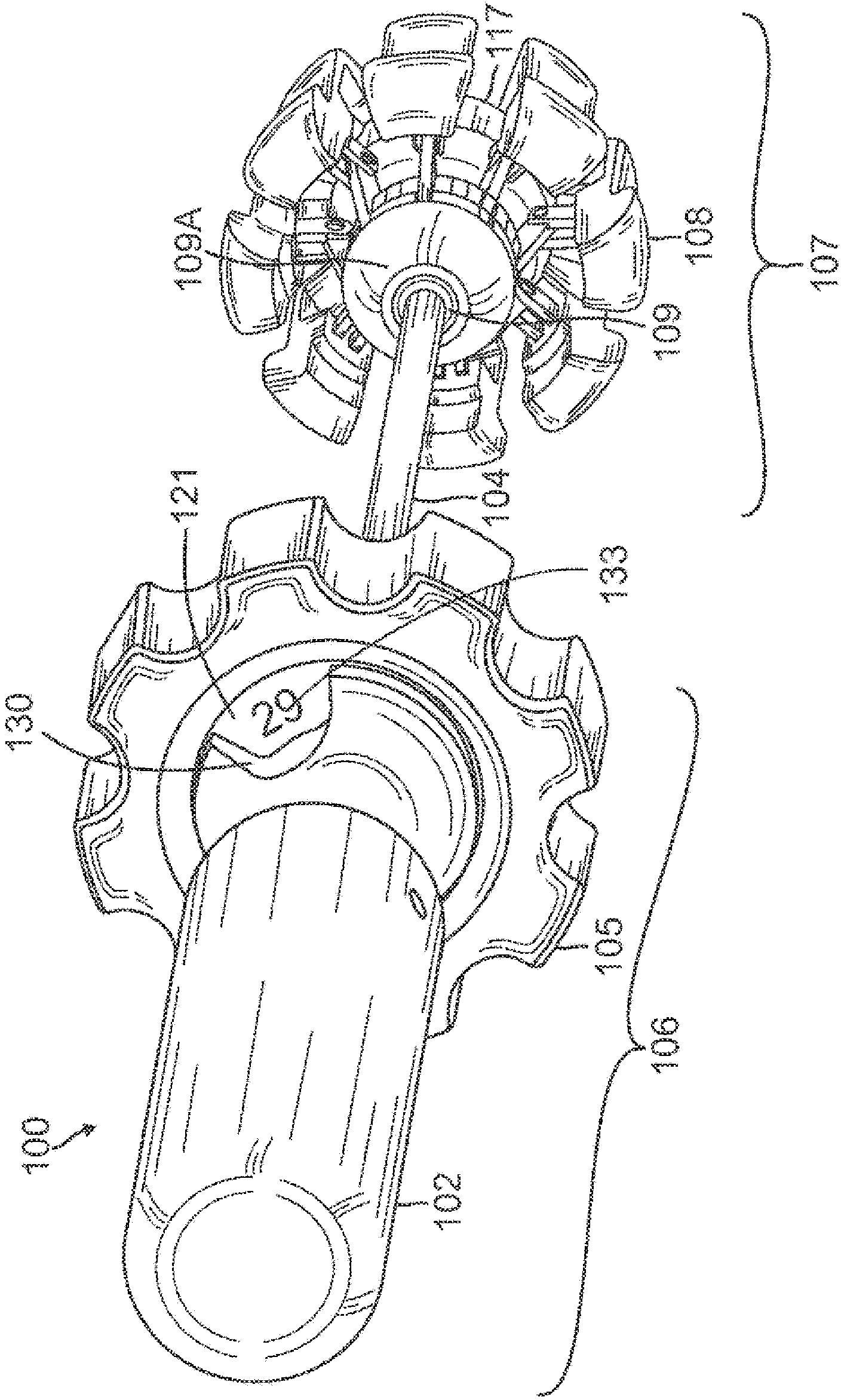
Figure 1 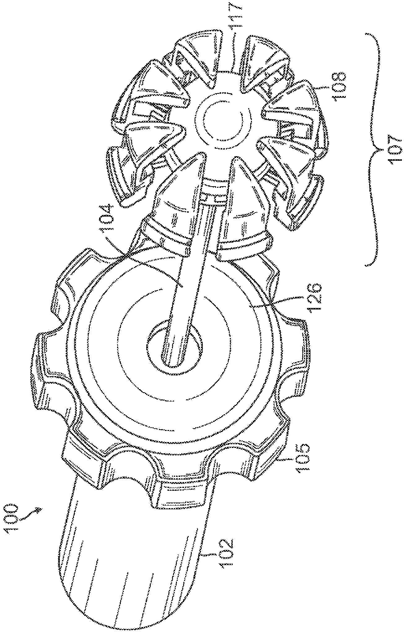
Figure 2 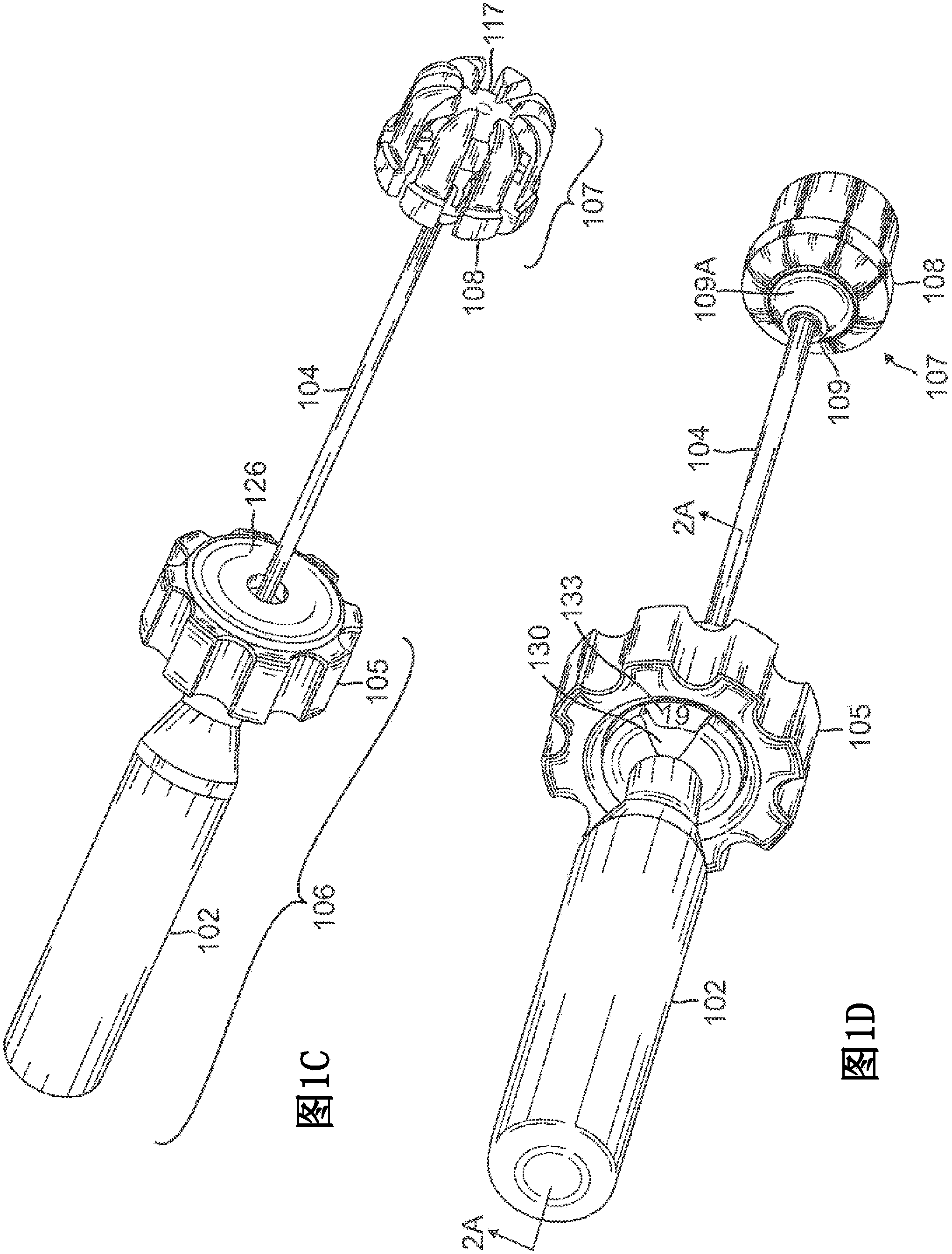
Figure 3
Abstract
Description
[0001] related application
[0002] This application claims priority under 35 U.S.C. §119 to U.S. Provisional Patent Application Serial No. 61 / 568,913, filed December 9, 2011. technical field
[0003] The present disclosure relates to methods and apparatus for determining valve annulus size. More specifically, the present disclosure relates to heart valve sizers. Background technique
[0004] Replacement of a diseased or malfunctioning heart valve requires accurate sizing of the valve annulus. After a diseased or malfunctioning heart valve has been removed, the surgeon measures the patient's valve annulus to determine the proper replacement valve size.
[0005] Conventional systems for measuring a patient's valve annulus include multiple discs of varying sizes that can be removably or fixedly attached to a rod. The size of each disc corresponds to the available valve size. The surgeon inserts the disc into the patient's valve annulus and checks the fit of the disc in the...
Examples
Embodiment Construction
[0054] refer to Figures 1A-1D , shows a first valve sizer 100 . Valve sizer 100 includes an elongated hollow shaft 104 extending along the length of the sizer. An actuator assembly 106 is coupled to the proximal end of the shaft 104, while a radially expandable sizing element 107 is coupled to the distal end. The shaft 104 is preferably malleable to ensure that it is flexible enough to allow the sizer 100 to enter the annulus from different angles or through curved or curved access pathways. The handle 102 is preferably stationary and serves to hold the valve sizer steady in the operator's hand.
[0055] refer to Figure 1C and 2A - 2C, the actuator assembly 106 includes the actuator 105 , the handle 102 , the clutch ring 121 (also referred to as the ring 121 ), and the clutch cover 126 installed in the actuator 105 . The handle 102 threadingly engages a tubular threaded portion 121B which terminates axially upwardly from a ring 121 which in turn is mounted on the shaft ...