
Multi-direction block forging device and process of special-shaped fuel injector body based on guide pin
A technology of closed forging and fuel injectors, which is applied in the direction of forging/pressing/hammer devices, manufacturing tools, metal processing equipment, etc., can solve the problems of long production cycle and low production efficiency, achieve simplified forging process, improve production efficiency and Product performance, the effect of realizing mechanization and automation
Patent Information
- Authority / Receiving Office
- CN · China
- Patent Type
- Patents(China)
- Current Assignee / Owner
- Publication Date
- 2017-06-13
Smart Images
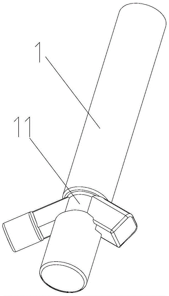
Figure 1 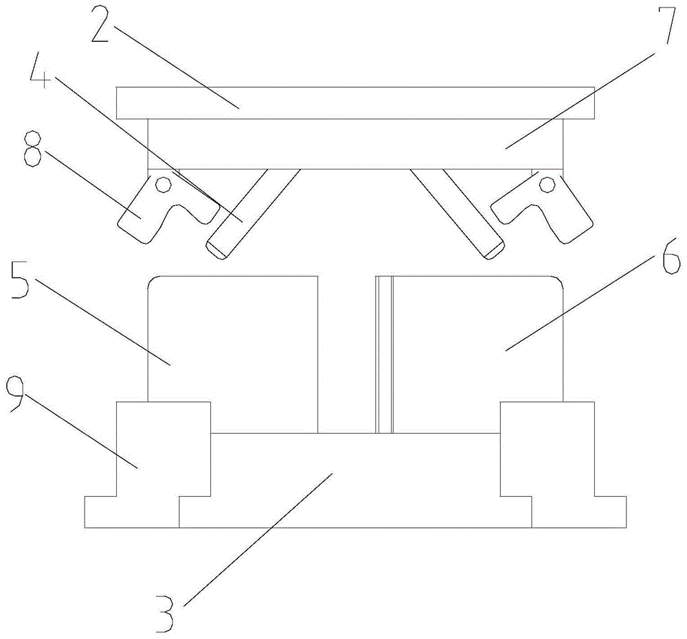
Figure 2 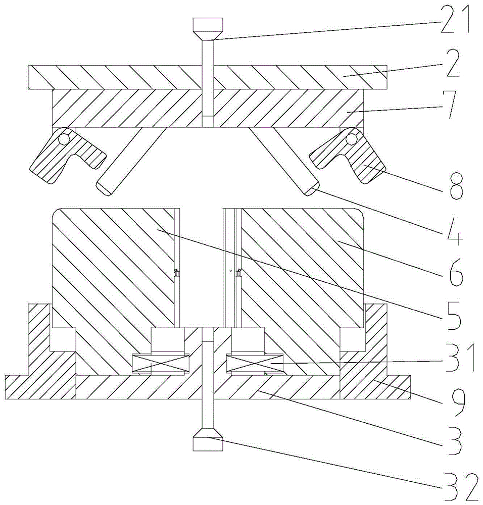
Figure 3
Abstract
Description
technical field
[0001] The invention belongs to the technical field of fuel injector body forging, and in particular relates to a block forging device and process for a special-shaped fuel injector body. Background technique
[0002] Such as figure 1 As shown, the special-shaped fuel injector body 1 has a small diameter of the intermediate transition section 11 and large dimensions at both ends. Generally, open die forging is used, and there are many forming processes, requiring more operators and equipment. After forging, it needs to be cut off. Flash has problems such as low production efficiency and long production cycle. Contents of the invention
[0003] The purpose of the present invention is to overcome the defects of low forging production efficiency and long production cycle of the fuel injector body in the prior art, and provide a multi-directional block forging device and its process based on the guide pin for the special-shaped fuel injector body.
[0004] Th...
Examples
Embodiment
[0030] Such as figure 2 and 3 As shown, a multidirectional block forging device based on guide pins for a special-shaped fuel injector body includes an upper mold 2 and a lower mold 3; the lower surface of the upper mold 2 is fixed with a fixing plate 7 by screws and pins, and the A pair of guide pins 4 arranged obliquely in the vertical direction are installed on the fixed plate 7, and the two guide pins 4 are in the shape of "eight"; the two sides of the lower mold 3 are provided with a left die 5 and a right die 6 ,Such as Figure 5 and 6 As shown, the left die 5 and the right die 6 are provided with an oblique guide hole 51 corresponding to the guide pin 4, the diameter of the oblique guide hole 51 is slightly larger than the diameter of the guide pin 4, and the oblique guide hole The end of the sliding hole 51 is provided with rounded corners; the left die 5 and the right die 6 are respectively provided with a cavity 61 matching the shape of the injector body 1, and t...