
Dead-weight pressing furnace door adopting rollers
A technology of rollers and furnace doors, which is applied in the direction of furnaces, furnace components, lighting and heating equipment, etc., can solve the problems of inability to adjust the sealing pressure of the furnace door, cannot be used repeatedly, and the workload of repairing is large, so as to achieve simple and time-saving installation, and two The effect of convenient maintenance and simple component configuration
Patent Information
- Authority / Receiving Office
- CN · China
- Patent Type
- Applications(China)
- Current Assignee / Owner
- Publication Date
- 2016-06-22
- Estimated Expiration
- Not applicable · inactive patent
Smart Images
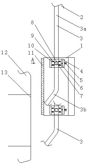
Figure 1
Abstract
Description
technical field
[0001] The invention relates to the technical field of industrial heat treatment furnaces, in particular to a self-weight pressing furnace door. technical background
[0002] In the form of industrial metal heat treatment furnace door, the existing technology mostly uses lever to compress the furnace door, or fixed self-pressing furnace door, its disadvantages and shortcomings: easy to damage, especially after the furnace door sealing material is worn, the furnace door cannot be sealed The adjustment of pressure cannot be used repeatedly, and the workload of repairing is heavy. Contents of the invention
[0003] In view of the deficiencies in the above industrial heat treatment furnaces, the purpose of the present invention is to provide a roller self-weight pressing furnace door, which adopts an adjustable roller and track structure to realize the sealing effect of the adjustable furnace door self-weight pressing.
[0004] The present invention is solved ...
Examples
Embodiment Construction
[0008] refer to figure 1 As shown, the self-weight pressing furnace door of the present invention is composed of a trolley, two hydraulic cylinders, a trolley door post, an outer sliding door frame, an inner layer sliding door frame, a sprocket wheel 8 and a roller chain, and the furnace door body 1 is fixed with Furnace door lining 11, adjusting screw 5 is installed on the positioning plate 4, and is fixed on the side of the furnace door body 1, the adjusting plate 6 has a long waist-shaped through-hole adjusting hole 10 for adjusting its installation position, and is fixed with a fulcrum 7. A sprocket 8 is installed on the support shaft 7, and the fixing screw 9 penetrates the adjusting hole 10 of the adjusting plate 6, and the adjusting plate 6 is fixedly installed on the positioning plate 4, and the adjusting plate 6 is positioned against the adjusting screw 5. By adjusting the adjusting screw 5 , the position of the adjusting plate 6 on the positioning plate 4 can be adju...