
Linear push bench slide mechanism
A sliding mechanism, straight line technology, applied in multi-purpose machinery, wood processing appliances, sawing components, etc., can solve the problems of poor straightness and poor wear resistance of linear push tables, achieve good straightness and improve sliding wear resistance. , the effect of easy assembly
Patent Information
- Authority / Receiving Office
- CN · China
- Current Assignee / Owner
- Publication Date
- 2017-04-12
- Estimated Expiration
- Not applicable · inactive patent
Smart Images
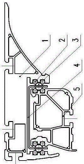
Figure 1
Abstract
Description
technical field
[0001] The invention relates to the field of woodworking machinery, in particular to a sliding mechanism for a high-precision linear woodworking push table. Background technique
[0002] The sliding structure of the current linear woodworking sliding table utilizes steel bars and steel balls to be assembled by gluing, and its disadvantages are poor wear resistance, poor straightness of the sliding table, and short service life. Contents of the invention
[0003] In order to solve the problems of poor wear resistance and poor straightness of the linear push table, the present invention invents a linear shaft-guided push table assembled with high-hardness chromium steel round rods and steel balls.
[0004] The technical solution of the present invention is a linear push platform sliding mechanism, which includes a base and a push platform top. Embedded in the convex edges on both sides of the table top, the inner side of the lower convex edge of the table to...
Examples
Embodiment Construction
[0008] The present invention will be further described below in conjunction with the accompanying drawings and embodiments.
[0009] As shown in the figure, there are drooping convex edges on both sides of the elongated push platform table top 1, the upper part of the elongated base 5 is embedded in the convex edges on both sides of the table top 1, and the inner side of the lower convex edge of the table top 1 Two upper and lower steel round bars 2 are installed on the upper and lower sides of the base 5 respectively. The steel round bars 2 on the convex edge of the table top 1 and the steel round bars 2 on both sides of the base 5 form a square angle, and a plurality of steel balls are embedded in the middle. 3. The steel ball 3 is fixed between the table 1 and the base 5 by the frame-like cage 4 . When pushing the push table top 1, the rolling of the steel ball 3 cooperates with the steel round bar 2 to make the push table top 1 slide.