
Damage Identification Method for Beam Structure Based on Modal Compliance Curvature Matrix Norm
A damage identification, matrix norm technology, applied in special data processing applications, geometric CAD, design optimization/simulation, etc., can solve problems such as damage location, inability to identify damage degree, etc., and achieve the effect of accurately identifying damage degree
Patent Information
- Authority / Receiving Office
- CN · China
- Patent Type
- Patents(China)
- Current Assignee / Owner
- Publication Date
- 2020-07-28
Smart Images
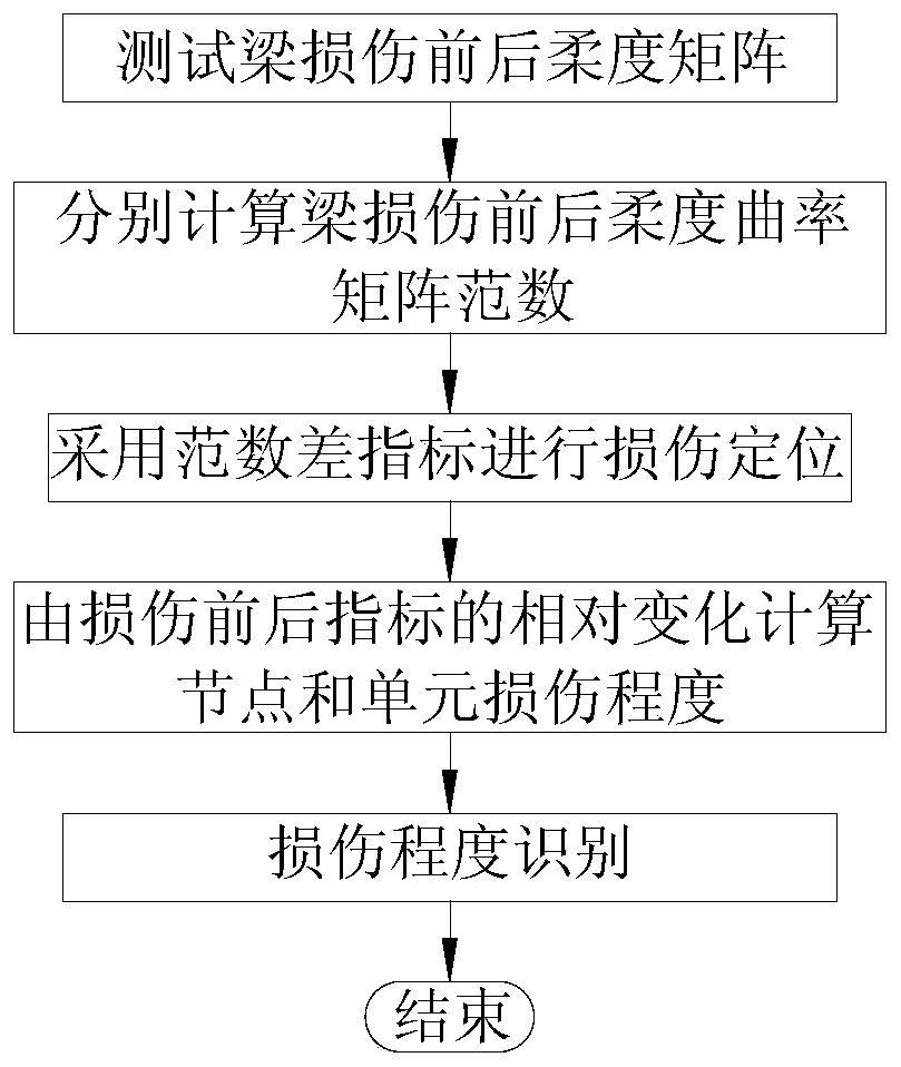
Figure 1 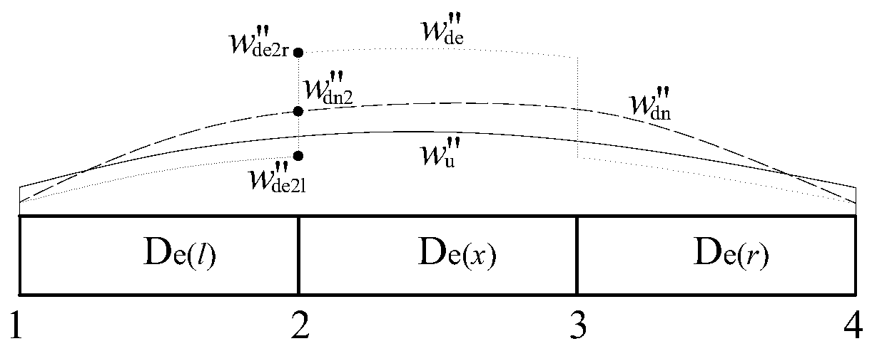
Figure 2 
Figure 3
Abstract
Description
technical field
[0001] The invention belongs to the technical field of structural health monitoring, and in particular relates to a beam structure damage identification method based on the modal flexibility curvature matrix norm in the beam structure non-destructive testing technology. Background technique
[0002] Bridge structures are widely used in highways, high-speed railways and other civil engineering fields that play an important role in national economic development. They are traffic throats and lifeline projects for national economic development. Its health status is increasingly concerned by the public. At present, many countries have installed health monitoring systems on newly-built important bridge structures, such as the Tsing Ma Bridge in Hong Kong, the Sutong Bridge, the Runyang Yangtze River Highway Bridge, and the Akashi Kaikyo Bridge in Japan. How to analyze a large amount of collected data and judge the state of the structure is a research hotspot at hom...
Examples
Embodiment 1
[0140] Embodiment one: if image 3 As shown, it is a simply supported beam with a span of 10m, which is equally divided into 20 units (the numbers in the circles in the upper row in the figure are the unit numbers, and the numbers in the lower row are the node numbers). The cross-sectional size is b×h=300mm×500mm, and the elastic modulus of the material is E=3.25×10 4 MPa, the density is 2500kg / m 3 . The damage of the unit is simulated by the reduction of the elastic modulus, and the damage conditions of the beam structure are shown in Table 1:
[0141] Table 1 Damage conditions of simply supported beams
[0142]
[0143] The specific implementation steps are as follows:
[0144] Step 1: Obtain the modal parameters of the three-span continuous beam before and after damage through finite element model simulation analysis, and calculate the flexibility matrix F from the first three vertical frequencies and mode shapes according to formula (1) u , F d .
[0145] Step 2:...
Embodiment 2
[0147] Embodiment two: if Figure 20 As shown, it is a three-span continuous beam finite element model, the span layout is 10m+15m+10m, 1.0m is divided into one unit, a total of 35 units, 36 nodes, (the number in the upper circle in the figure is the unit number , the numbers in the lower row are node numbers). The cross-sectional size is b×h=300mm×500mm, and the elastic modulus of the material is E=3.25×10 4 MPa, the density is 2500kg / m 3 . The damage of the unit is simulated by the reduction of the elastic modulus, and the damage conditions of the beam structure are shown in Table 2:
[0148] Table 2 Damage conditions of three-span continuous beams
[0149]
[0150] The specific implementation steps are as follows:
[0151] Step 1: Obtain the modal parameters of the three-span continuous beam before and after damage through finite element model simulation analysis, and calculate the flexibility matrix F from the first three vertical frequencies and mode shapes accord...