
Improved new energy straw coal processing equipment
A technology for processing equipment and straw coal, applied in the field of improved new energy straw coal processing equipment, can solve the problems of poor molding effect, single molding specification, narrow application range, etc. The effect of tightness
Patent Information
- Authority / Receiving Office
- CN · China
- Current Assignee / Owner
- Publication Date
- 2017-12-05
- Estimated Expiration
- Not applicable · inactive patent
Smart Images
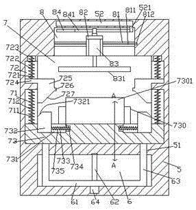
Figure 1 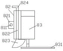
Figure 2 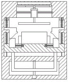
Figure 3
Abstract
Description
technical field
[0001] The invention relates to the technical field of new energy, in particular to an improved new energy straw coal processing equipment. Background technique
[0002] Straw is a good clean and renewable energy source. All combustible biomass such as crop straws, leaves, dead branches, sawdust, and weeds can be used as raw materials for straw coal. The cost of making straw coal is low, and straw coal is used Convenient and good combustion effect, especially a must for biomass power plants. In the production process of straw coal, it needs to be pulverized, pressurized, and densified to form. Traditional pressurization machines have single molding specifications, poor molding effect, and a large amount of straw ash will be raised during the pressurization process, which will affect the health of workers. In addition, the existing pressurization equipment is expensive, large in size, and narrow in scope of application. . Contents of the invention [0003...
Examples
Embodiment Construction
[0022] Such as Figure 1-Figure 4 As shown, an improved new energy straw coal processing equipment of the present invention includes a frame body 5, a pressurizing part 7 is arranged inside the frame body 5, and a pressurizing part 7 is arranged inside the frame body 5 below the There is a lifting chamber 6, and the top surface of the pressurizing part 7 is provided with a top groove 8 extending left and right, the top groove 8 is provided with a sliding block 82, and the front end surface of the sliding block 82 is fixed with a A pressure driving device 83, the bottom of the pressure driving device 83 is provided with a pressure terminal 831 that extends into the pressure part 7 and is screwed and connected. The inner walls of the left and right sides of the pressure part 7 are respectively provided The first guide groove 71 and the second guide groove 72 arranged above the first guide groove 71, the first guide groove 71 is provided with a first guide rod 711 extending up an...