
Megnetron sputtering cathode system
A magnetron sputtering and cathode technology, applied in the field of sputtering coating, can solve the problems of affecting the coating quality and uneven loss
Patent Information
- Authority / Receiving Office
- CN · China
- Patent Type
- Applications(China)
- Current Assignee / Owner
- Publication Date
- 2018-05-04
- Estimated Expiration
- Not applicable · inactive patent
Smart Images
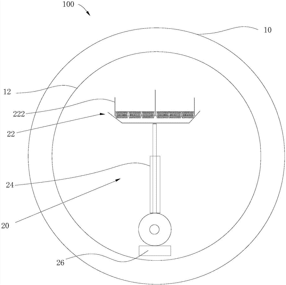
Figure 1 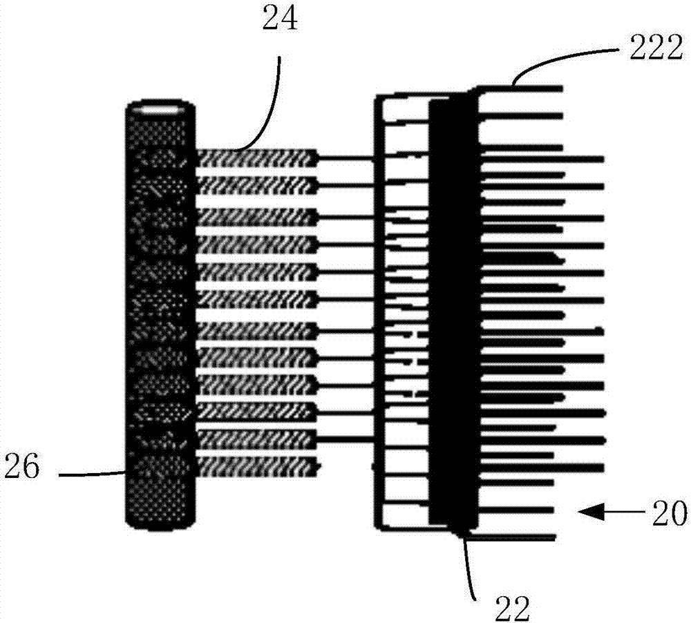
Figure 2
Abstract
Description
technical field
[0001] The invention relates to the field of sputtering coating, in particular to a magnetron sputtering cathode system. Background technique
[0002] In the current magnetron sputtering cathode system, the target produces boundary effects under the action of a fixed magnetic field, and the loss is uneven, which affects the coating quality. Contents of the invention
[0003] The present invention aims to solve one of the technical problems in the related art at least to a certain extent. Therefore, the present invention proposes a magnetron sputtering cathode system.
[0004] The magnetron sputtering cathode system of the embodiment of the present invention comprises:
[0005] ring targets; and
[0006] A magnetic assembly disposed within the annular target is rotated, and magnetic field lines of the magnetic assembly pass through the annular target.
[0007] In the embodiment of the present invention, the magnetic assembly moves relative to the target,...
Examples
Embodiment Construction
[0027] Embodiments of the present invention will be further described below in conjunction with the accompanying drawings. The same or similar reference numerals in the drawings represent the same or similar elements or elements having the same or similar functions throughout.
[0028] In addition, the embodiments of the present invention described below in conjunction with the accompanying drawings are exemplary, and are only used to explain the embodiments of the present invention, and should not be construed as limiting the present invention.
[0029] see figure 1 and figure 2 , the magnetron sputtering cathode system 100 according to the embodiment of the present invention includes an annular target 10 and a magnetic assembly 20 rotatably arranged in the annular target 10 , and the magnetic field lines of the magnetic assembly 20 pass through the annular target 10 .
[0030] In the embodiment of the present invention, the magnetic assembly 20 moves relative to the annul...