
Universal-type automatic gas supply joint
A universal and automatic technology, applied in the direction of pipes/pipe joints/fittings, gas/liquid distribution and storage, connections with fluid cut-off devices, etc., it can solve the problems of poor automation, low work efficiency and increased unsafe factors and other problems, to achieve the effect of strong receiving ability and good sealing effect
Patent Information
- Authority / Receiving Office
- CN · China
- Patent Type
- Applications(China)
- Current Assignee / Owner
- Publication Date
- 2018-05-25
Smart Images
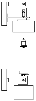
Figure 1 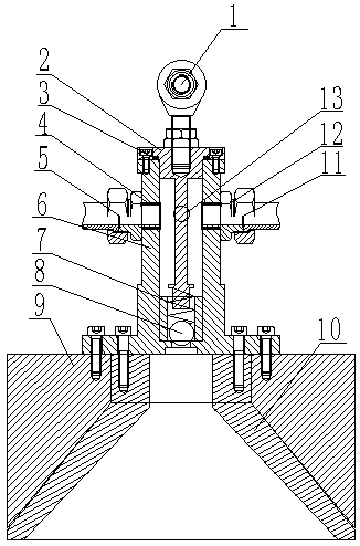
Figure 2 
Figure 3
Abstract
Description
technical field
[0001] The invention relates to the field of pressure gas delivery, in particular to a universal automatic air supply joint. Background technique
[0002] In industrial production, many processes need to transport pressure gas from fixed equipment to mobile equipment. The traditional method is usually that the workers manually connect the pipelines on the fixed equipment and mobile equipment with quick-plug joints, and then Ventilation work has low work efficiency and poor automation; if the work equipment is still in a complex environment such as high temperature, high risk, and radiation, manual operation will increase many unsafe factors. Contents of the invention
[0003] The invention aims to eliminate the safety hazards of pressure gas transportation operators in complex environments such as high temperature, high risk and radiation, improve efficiency, realize the automation of pressure gas transportation production, and provide a universal automatic...
Examples
Embodiment Construction
[0035] The present invention will be further described below in conjunction with the accompanying drawings and specific embodiments, without limiting the scope of protection.
[0036] A universal automatic air supply joint is characterized in that the device includes: a receiving mechanism, a transmitting mechanism, a balance mechanism and a mounting bracket. The structural diagram of the joint is shown in figure 1 shown.
[0037] like figure 2 As shown, the receiving mechanism includes: upper joint bearing (1), receiving mechanism base (2), receiving mechanism spool (6), steel ball compression spring (7), steel ball (8), receiving mechanism counterweight (9) , Guide cone (10). like Image 6 As shown, a circle of split holes (49) of the same size is provided in the cavity of the spool (6) of the receiving mechanism, and the split holes (49) intersect with the inner hole. The steel ball (8) is placed at the valve port in the cavity of the spool (6) of the receiving mechani...