
A method and device for forming by internal pressure expansion and reverse deep drawing
A technology of reverse deep drawing and bulging, which is applied in the direction of forming tools, metal processing equipment, manufacturing tools, etc. It can solve problems such as high risk, difficult to guarantee weld quality, complicated calculation and blanking, etc., and achieve low pressure requirements , energy saving, simple structure effect
Patent Information
- Authority / Receiving Office
- CN · China
- Patent Type
- Patents(China)
- Current Assignee / Owner
- Publication Date
- 2020-01-10
Smart Images
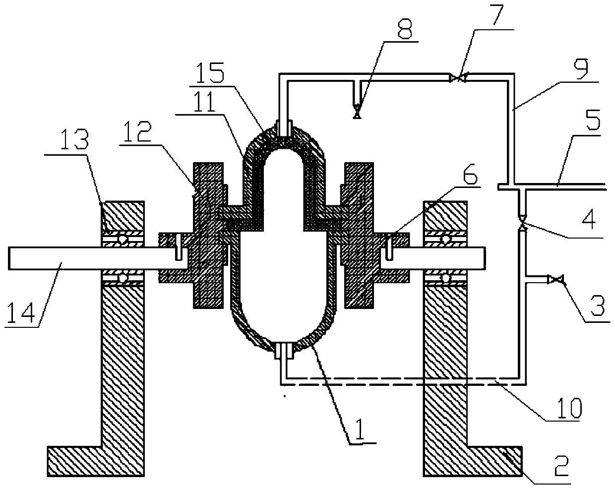
Figure 1
Abstract
Description
technical field
[0001] The invention belongs to the technical field of plastic forming equipment, and in particular relates to an internal compression expansion type and reverse deep drawing forming device, and also relates to an internal compression expansion type and reverse deep drawing forming method. Background technique
[0002] Pressure vessels are important equipment in petroleum, chemical, energy and other industries. With the development of my country's social economy, pressure vessels in nuclear power, coal chemical industry, oil refining, petrochemical, military and other industries are showing a trend of large-scale development, especially large With the appearance of hydrogenation reactors with large diameter and large wall thickness, coal liquefaction reactors, nuclear reactor shells, etc., large-scale heads have emerged as the times require. In order to ensure long-term high-efficiency operation of equipment under high temperature and high pressure, the size o...
Examples
Embodiment Construction
[0020] The present invention will be described in detail below in conjunction with the accompanying drawings and specific embodiments.
[0021] The present invention is an internal compression expansion type and reverse deep drawing forming device, such as figure 1 As shown, the base 2 comprising a built-in cavity has a shaft 14 passing through the same position on the opposite side of the base 2, and one end of each shaft 14 outside the base 2 is connected to the drive mechanism, and the other end of each shaft 14 is The frame 12 is connected by the pin 6, so that the shaft 14 can drive the frame 12 to rotate together, and an upper mold 11 is connected between the two frames 12, and a lower mold 1 is connected between the two frames 12, and the upper mold 11. A hole is respectively opened on the top of the lower mold 1, and the upper mold 11 and the lower mold 1 are respectively connected to the same fluid medium pressure transmission system through the holes, and the fluid m...