
Fiber optic junction box with controllable incoming lines
A fiber optic junction box and cable inlet technology, applied in the field of junction boxes, can solve the problems of cumbersome and inconvenient, easy to cause accidents, and entanglement of incoming wires, so as to reduce the opening and closing time, reduce the difficulty of opening, and the opening structure is simple Effect
Patent Information
- Authority / Receiving Office
- CN · China
- Patent Type
- Patents(China)
- Current Assignee / Owner
- Publication Date
- 2020-07-21
Smart Images
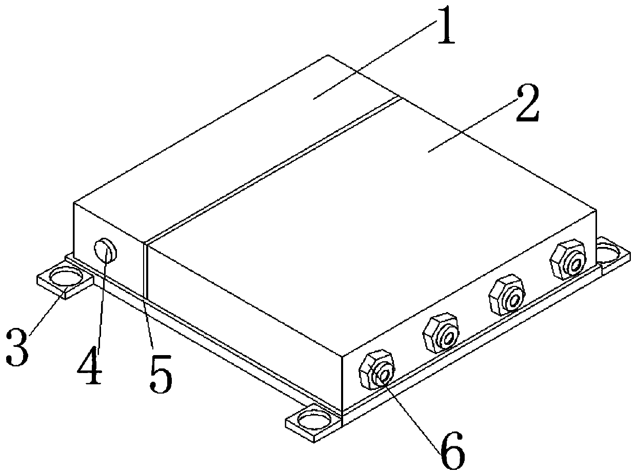
Figure 1 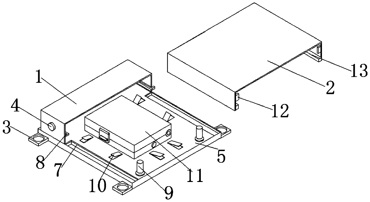
Figure 2 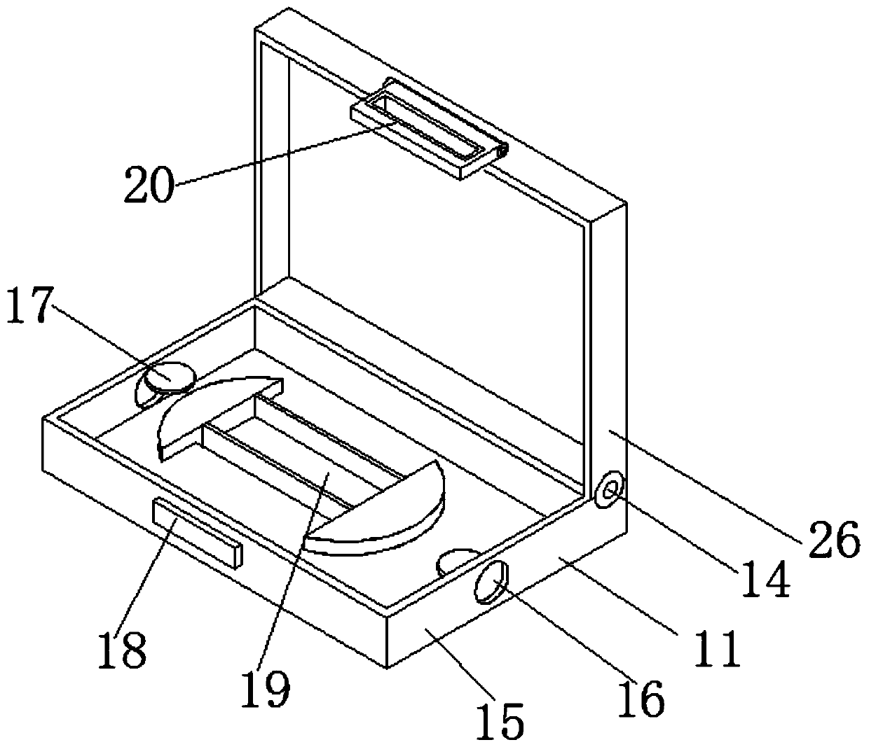
Figure 3
Abstract
Description
technical field
[0001] The invention relates to the technical field of junction boxes, in particular to an optical fiber junction box capable of controlling incoming lines. Background technique
[0002] In home decoration, the junction box is one of the electrical accessories, because the wires used for decoration pass through the wire tube, and the junction box is used as a transition at the joint of the wire (for example, the line is relatively long, or the wire tube needs to be cornered). Use, the wire tube is connected to the junction box, and the wires in the wire tube are connected in the junction box to protect the wires and connect the wires. This is the junction box. The general junction box is composed of a box cover, a box body, a terminal block, a diode, a connecting wire, and a connector, and an optical fiber junction box is a box for protecting the optical cable and the pigtail at the end of the laying of the optical cable. It is mainly used for indoor optical ...
Examples
Embodiment Construction
[0022] The following will clearly and completely describe the technical solutions in the embodiments of the present invention with reference to the accompanying drawings in the embodiments of the present invention. Obviously, the described embodiments are only some, not all, embodiments of the present invention. Based on the embodiments of the present invention, all other embodiments obtained by persons of ordinary skill in the art without making creative efforts belong to the protection scope of the present invention.
[0023] see Figure 1-6 , an optical fiber junction box that can control incoming lines, including a base plate 5, one end of the base plate 5 is fixedly connected with a fixed cover 1, and a pressing block 4 is arranged on the outside of the fixing cover 1, and a spring 21 is connected to the inner side of the pressing block 4, and The end of the spring 21 is connected with a fixed block 22, the outside of the spring 21 is connected with a connecting rod 23, a...