
Anti-blocking plane gate
A technology of plane gate and end face, which is applied in the field of water conservancy engineering, can solve the problems of difficult to clean debris, the gate has no filtering function, and is easy to be blocked, so as to achieve the effect of conveniently cleaning debris, improving water filtration efficiency, and preventing blockage
Patent Information
- Authority / Receiving Office
- CN · China
- Current Assignee / Owner
- Publication Date
- 2019-05-07
Smart Images

Figure 1 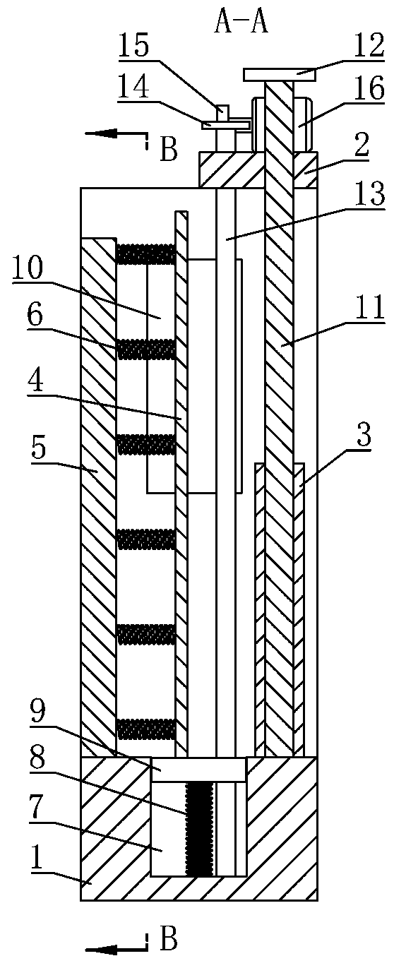
Figure 2 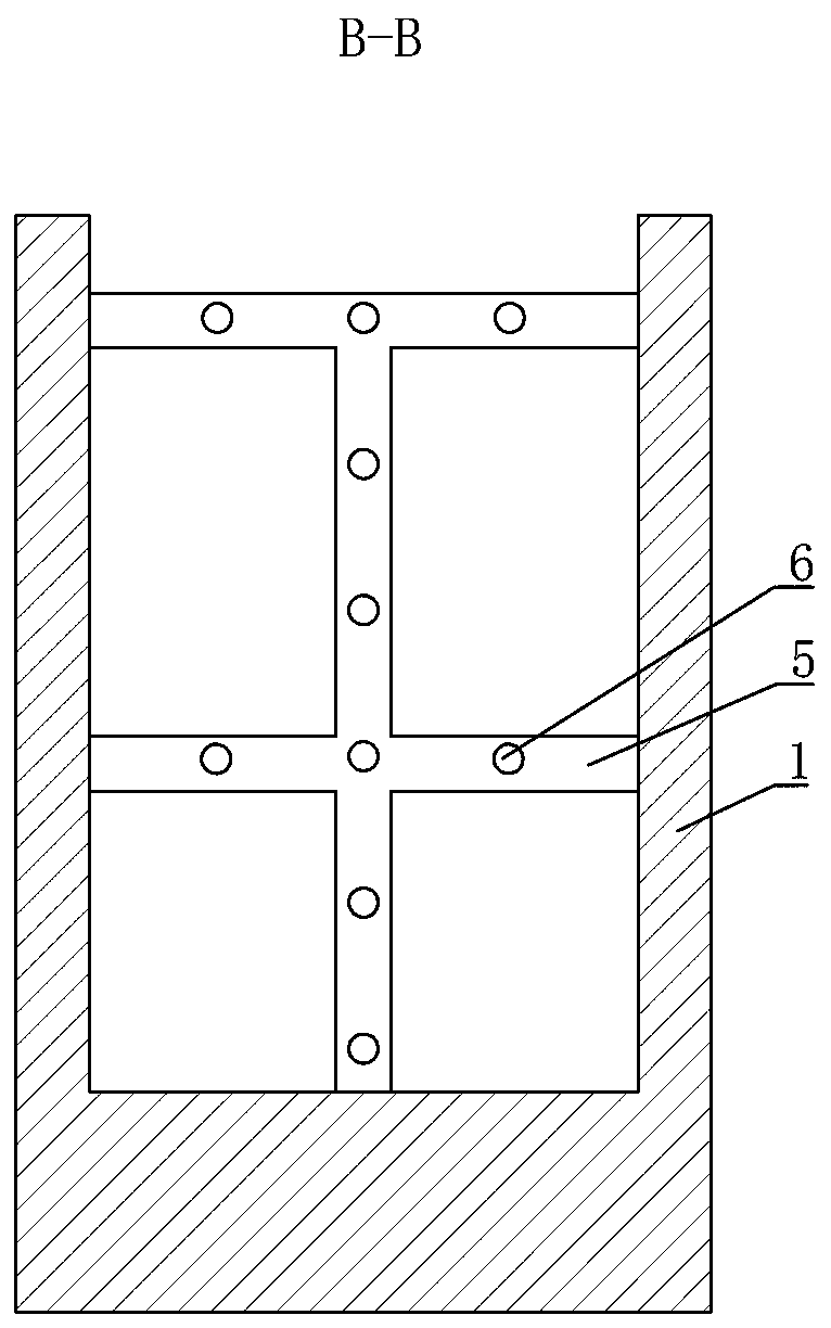
Figure 3
Abstract
Description
technical field
[0001] The invention relates to the technical field of hydraulic engineering, in particular to an anti-blocking plane gate. Background technique
[0002] A water conservancy project is a project built for the purpose of controlling and allocating natural surface water and groundwater to achieve the purpose of eliminating harm and benefiting. Water conservancy projects need to build dams, embankments, spillways, sluices, water inlets, channels, ferries, rafts, and fisheries. different types of hydraulic structures, such as roads, to achieve their goals. In rural areas, many irrigation systems use gates to release water.
[0003] The existing gate does not have the ability to filter debris such as large stones or garbage when it is in use, which will cause certain damage to crops, and is prone to blockage after long-term use, which is difficult to clean, increases the labor intensity of workers, and has low use efficiency. . SUMMARY OF THE INVENTION [000...
Examples
Embodiment Construction
[0012] The specific embodiments of the present invention will be further described in detail below with reference to the accompanying drawings.
[0013] Depend on Figure 1 to Figure 5 Given, including a U-shaped frame body 1, a support plate 2 is fixed above the frame body 1, a baffle plate 3 located on the front side of the frame body 1 and can be moved up and down is slidably connected in the frame body 1, and a baffle plate located in the frame body 1 is provided in the frame body 1. 3. The filter plate 4 at the rear and can slide back and forth in the frame body 1, the support frame 5 placed left and right is fixed on the rear side of the frame body 1, and the rear end surface of the filter plate 4 is fixedly connected with the support frame 5 through a plurality of first springs 6. The bottom of the body 1 is provided with a groove 7 in the left and right directions and located under the filter plate 4. The bottom of the groove 7 is connected with a scraper 9 that can mo...