
Semiconductor single crystal production apparatus
Patent Information
- Authority / Receiving Office
- US · United States
- Current Assignee / Owner
- Publication Date
- 2010-08-26
- Estimated Expiration
- Not applicable · inactive patent
Smart Images
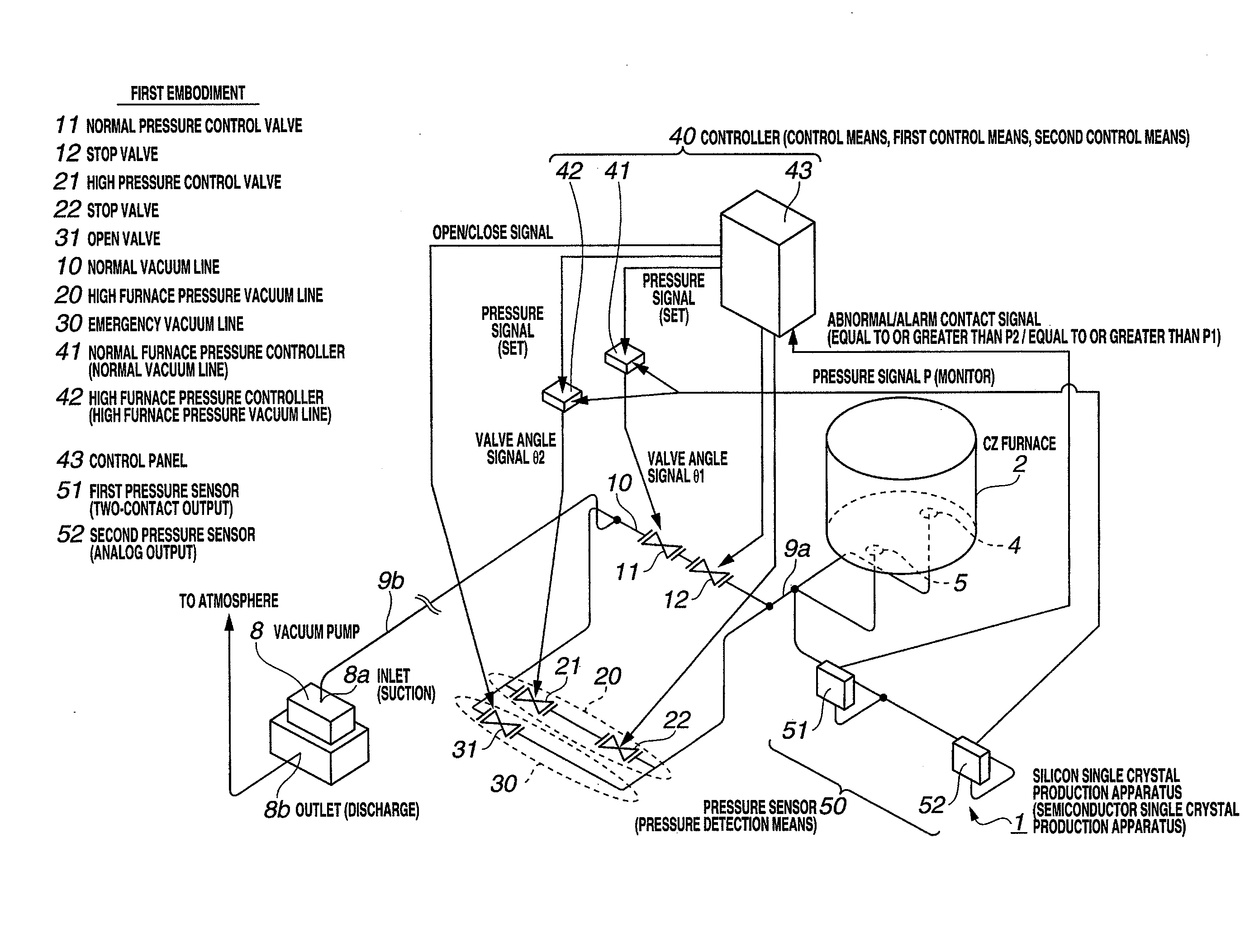
Figure 1 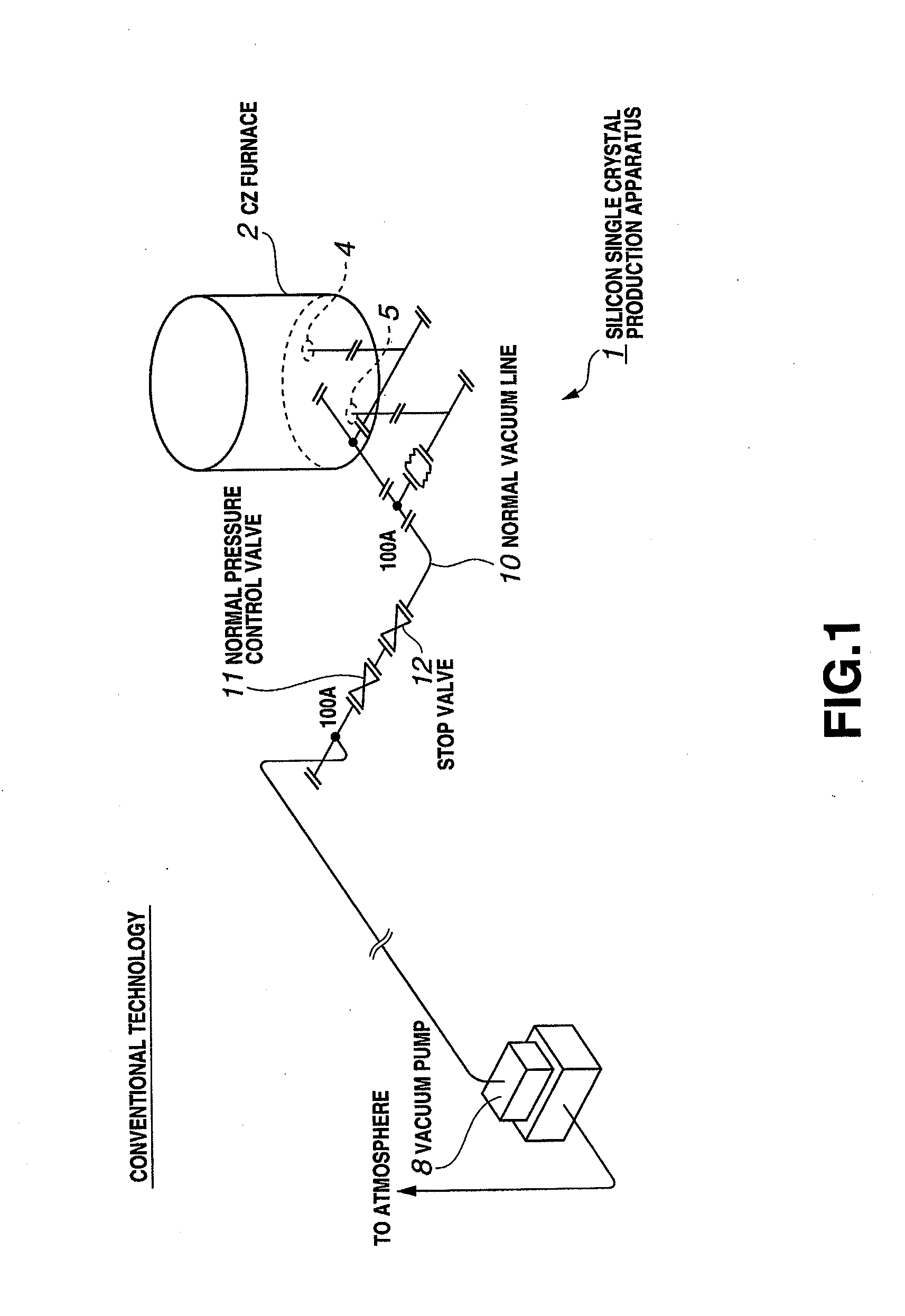
Figure 2 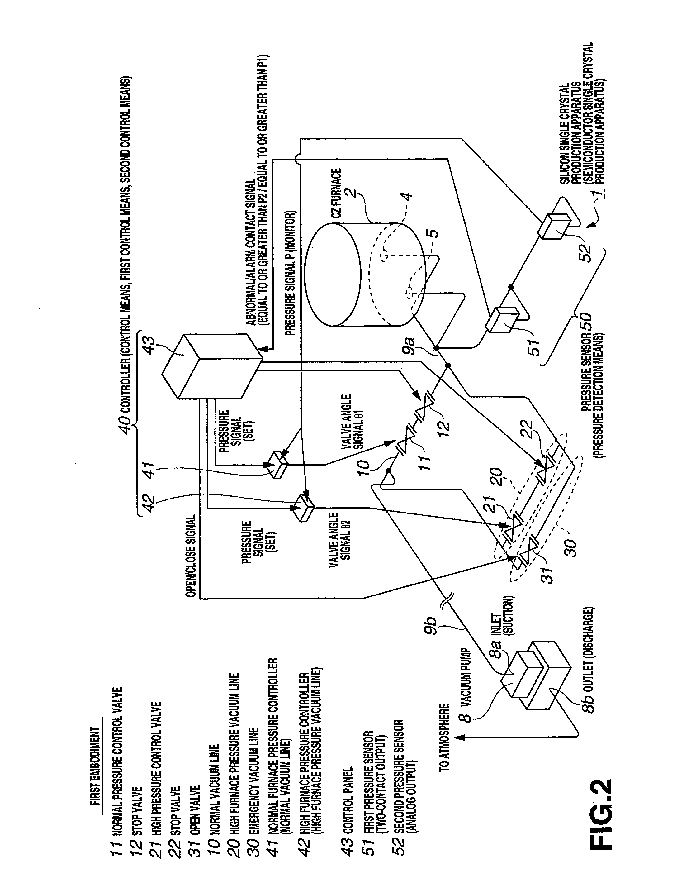
Figure 3
Abstract
Description
TECHNICAL FIELD
[0001] The present invention relates to a semiconductor single crystal production apparatus, and more particularly to an apparatus in which an inert gas is supplied in a furnace and a semiconductor single crystal doped with a dopant is produced inside the furnace, while discharging the gas in the furnace from an outlet (discharge) via a vacuum line.BACKGROUND ARTConventional Technology
[0002] A demand was created in recent years for high-yield production of silicon wafers for use in discrete semiconductor devices and the like, namely, low-resistance silicon wafers that have N-type electric characteristics and are doped to a high concentration with a volatile dopant.
[0003] Examples of N-type volatile dopants referred to herein include antimony Sb, red phosphorus P, and arsenic As. The low resistance is a resistance value equal to or lower than 20 / 1000 Ωcm.
[0004] FIG. 1 shows a configuration of a conventional silicon single crystal production apparatus 1. This conventional a...
Examples
first embodiment
[0090]FIG. 2 shows the configuration of a silicon single crystal production apparatus 1 of the embodiment. The apparatus 1 of this embodiment serves to produce a volatile N-type high-concentration and low-resistance silicon wafer (high furnace pressure product) and a silicon wafer (normal furnace pressure product) with a concentration lower and a resistance higher than those of the high furnace pressure product. The silicon single crystal production apparatus 1 is installed in a clean room.
[0091]The “N-type volatile dopant” as referred to herein is antimony Sb, red phosphorus P, and arsenic As, etc. The “low resistance” is taken as a resistance value that is equal to or lower than 20 / 1000 Ωcm.
[0092]Outlets (discharge) 4, 5 of a CZ furnace 2 are provided on the lower side of the CZ furnace 2. In the present embodiment, a structure is assumed in which gas is discharged from the lower side of the CZ furnace 2, but gas outlets (discharge) may be provided in any location of the CZ furnac...
second embodiment
[0168]FIG. 5 shows a configuration in which, compared with FIG. 2, normal vacuum line 10 and emergency vacuum line 30 except for the high furnace pressure vacuum line 20 are omitted and only the high furnace pressure vacuum line 20 is provided as a vacuum line linking the CZ furnace 2 to the vacuum pump 8.
[0169]With the second embodiment, the above-described effect A can be obtained.
third embodiment
[0170]FIG. 6 shows a configuration in which, compared with FIG. 2, normal vacuum line 10 except for the high furnace pressure vacuum line 20 and emergency vacuum line 30 is omitted and only the high furnace pressure vacuum line 20 and emergency vacuum line 30 are provided as vacuum lines linking the CZ furnace 2 to the vacuum pump 8.
[0171]With the third embodiment, the above-described effects A and B can be obtained.