
AGV loading platform
A loading platform and loading box technology, applied in the direction of non-electric variable control, instruments, two-dimensional position/channel control, etc., can solve the problems of difficulty in ensuring the safety of transported items and low safety, and achieve the prevention of item loss, Easy to carry and ensure the effect of accuracy
Patent Information
- Authority / Receiving Office
- CN · China
- Patent Type
- Applications(China)
- Current Assignee / Owner
- Publication Date
- 2019-11-05
Smart Images
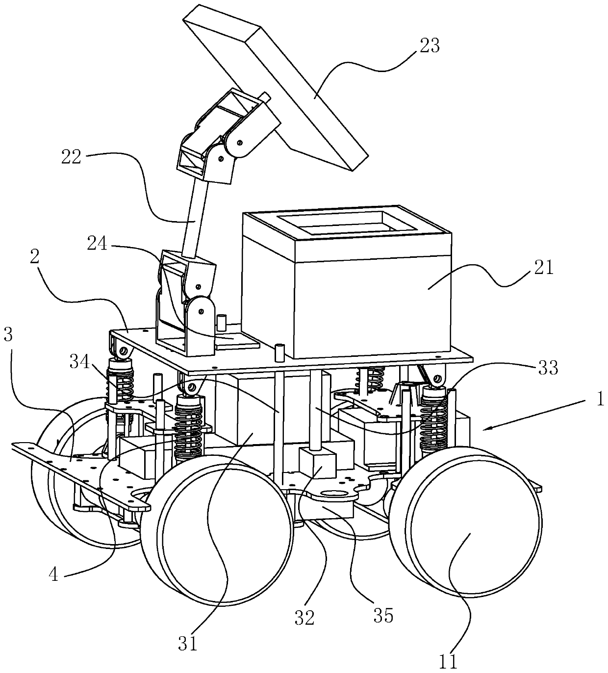
Figure 1 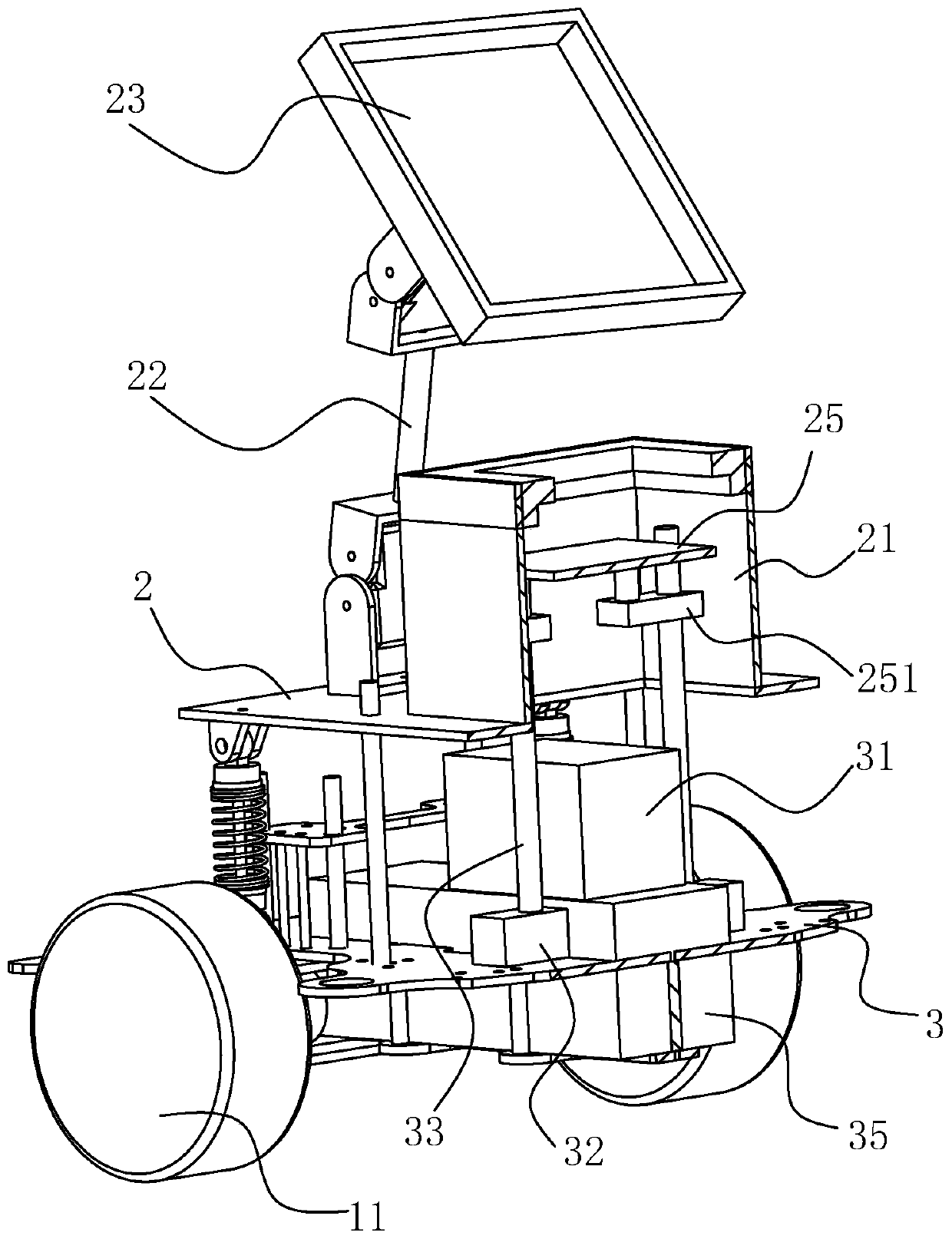
Figure 2 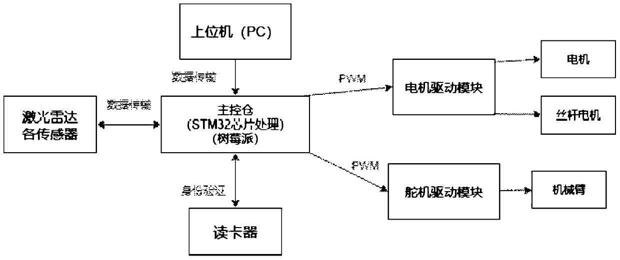
Figure 3
Abstract
Description
technical field
[0001] The invention relates to the field of automatic guided transport robots, in particular to an AGV loading platform. Background technique
[0002] In the development of modern science and technology, electronization, informatization, networking and intelligence have become the development trend, and AGV (Automatic Guided Transport Vehicle) is the perfect expression of this development trend. At present, the automatic guided AGV loading platform is more and more widely used in industrial production practice. Due to its high automation and intelligent characteristics, the factory not only saves labor costs and production costs, but also improves production efficiency and production cycle. AGV is also known as unmanned guided vehicle, automatic guided vehicle. Its notable feature is unmanned driving. The AGV is equipped with an automatic guidance system, which can ensure that the system can automatically drive along a predetermined route without manual pil...
Examples
Embodiment Construction
[0023] The specific implementation manners of the present invention will be further described below in conjunction with the accompanying drawings, and this embodiment does not constitute a limitation to the present invention.
[0024] A kind of AGV loading platform, such as figure 1 As shown, it includes a frame body 1. The frame body 1 includes an upper load-bearing plate 2 and a lower load-bearing plate 3. The upper load-bearing plate 2 slides up and down and is connected to the lower load-bearing plate 3. Two penetrating upper load-bearing plates are symmetrically fixed on the lower load-bearing plate 3. 2 guide rod 34 provided; four shock absorbers 4 are connected between the upper bearing plate 2 and the lower bearing plate 3, respectively located at the four corners of the upper bearing plate 2, and the upper ends of the shock absorbers 4 are hinged on the upper bearing plate 2 , the lower end is hinged to the lower bearing plate 3.
[0025] like figure 1 As shown, fou...