
Ferris wheel emergency rescue device and control method thereof
A technology of emergency rescue and control methods, applied in entertainment devices, big wheels, Russian swings, etc., can solve the problems of low rescue efficiency and achieve the effects of quick operation, firm and stable installation, and easy disassembly and assembly
Patent Information
- Authority / Receiving Office
- CN · China
- Current Assignee / Owner
- Publication Date
- 2020-03-17
Smart Images
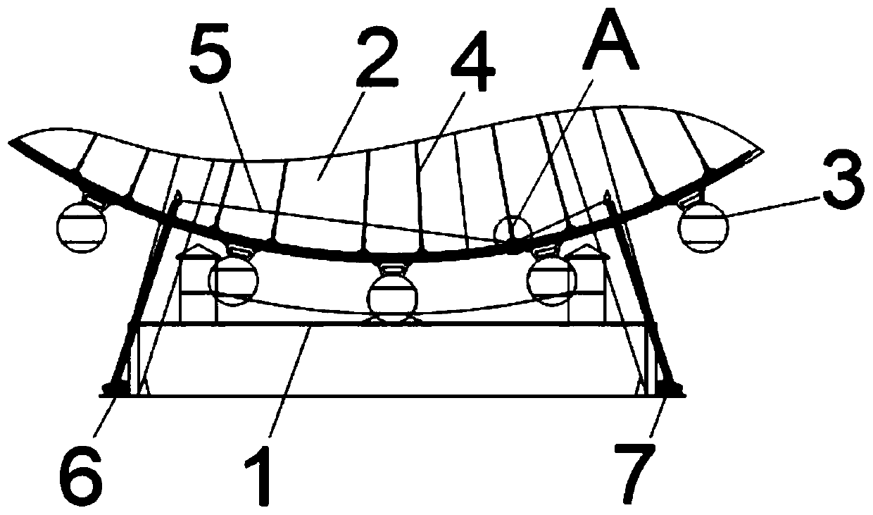
Figure 1 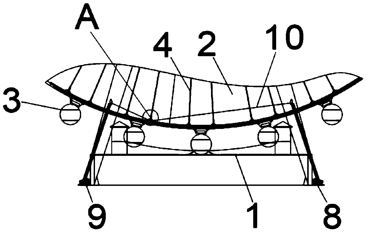
Figure 2 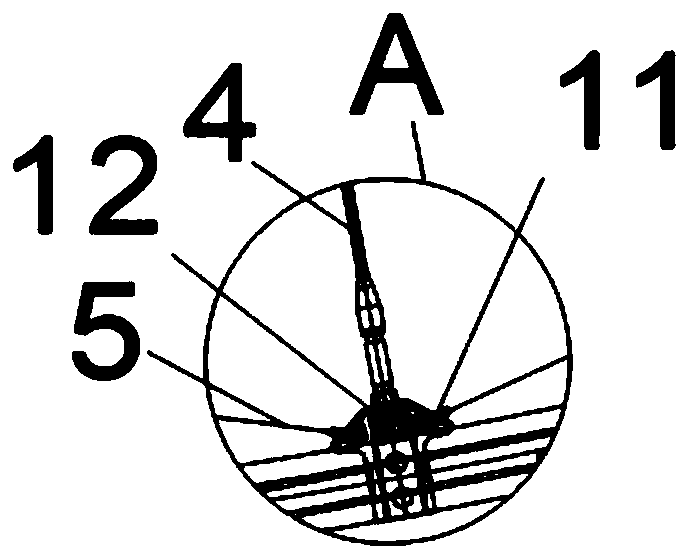
Figure 3
Abstract
Description
technical field
[0001] The invention relates to the technical field of a Ferris wheel rescue device and a control method thereof, in particular to a Ferris wheel emergency rescue device and a control method thereof. Background technique
[0002] The Ferris wheel is a large-scale runner-shaped mechanical building facility, and the cockpit for passengers is hung on the edge of the wheel. Passengers sit on the Ferris wheel and slowly turn up, overlooking the surrounding scenery from a height. The most common Ferris wheel generally appears in amusement parks or theme parks and garden fairs. As a kind of amusement park motor game, it is collectively called the "Three Treasures of Paradise" together with roller coasters and carousels. However, the Ferris wheel often exists alone on other occasions, and is usually used as a viewing platform for activities.
[0003] With the continuous development of the times, people are more and more fond of riding equipment such as Ferris wheel...
Examples
Embodiment 1
[0024] see Figure 1-5 , the present embodiment provides a Ferris wheel emergency rescue device, which is specifically as follows:
[0025] Ferris wheel emergency rescue device includes passenger platform 1, Ferris wheel 2, sightseeing cabin 3, rotating rod 4, wire rope A5, first hoist 6, second hoist 7, third hoist 8, fourth hoist 9, wire rope B10, hanging ears 11 and a hook 12, the top of the passenger platform 1 is provided with a Ferris wheel 2, the bottom of the Ferris wheel 2 is provided with several groups of sightseeing cabins 3, the lower left end of the passenger platform 1 is provided with a first winch 6, and The lower right end of the passenger platform 1 is provided with a second hoist 7, the upper left end of the passenger platform 1 is provided with a third hoist 8, the upper right end of the passenger platform 1 is provided with a fourth hoist 9, and the inside of the Ferris wheel 2 A rotating rod 4 is provided, the outer side of the rotating rod 4 is connect...
Embodiment 2
[0030] see Figure 1-5 , the present embodiment provides a control method for a Ferris wheel emergency rescue device, comprising the following steps:
[0031] The control system includes a monitoring sensor A13, a monitoring sensor B14, a monitoring sensor C15, an auxiliary unit 16, a main control chip 17, an alarm unit 18 and a power supply unit 19) The control system is installed in the operation center room of the passenger platform 1, The monitoring sensor A13, the monitoring sensor B14, and the monitoring sensor C15 are arranged outside the passenger platform 1. The monitoring sensor A13, the monitoring sensor B14, and the monitoring sensor C15 are electrically connected in parallel with the auxiliary unit 16 through wires, and the auxiliary unit 16 is electrically connected in parallel with the auxiliary unit 16. The wireless information communication is electrically connected to one side of the main control chip 17, and the other side of the main control chip 17 is elec...
Embodiment 3
[0035] see Figure 1-5 , the present embodiment provides a control method for a Ferris wheel emergency rescue device, comprising the following steps:
[0036]First, the control system includes a monitoring sensor A13, a monitoring sensor B14, a monitoring sensor C15, an auxiliary unit 16, a main control chip 17, an alarm unit 18 and a power supply unit 19, and the control system is installed in the operation center room of the passenger platform 1 Among them, the monitoring sensor A13, the monitoring sensor B14, and the monitoring sensor C15 are arranged outside the passenger platform 1, and the monitoring sensor A13, the monitoring sensor B14, and the monitoring sensor C15 are electrically connected in parallel with the auxiliary unit 16 through wires, and the auxiliary unit 16 is electrically connected to one side of the main control chip 17 through wireless information communication, the other side of the main control chip 17 is electrically connected to the alarm unit 18, ...