
PLC control box with good heat dissipation and dehumidification performance
A control box and performance technology, applied in logic controllers for automation/industrial process control, cooling/ventilation/heating transformation, casings/cabinets/drawer parts, etc., can solve the problem of water ingress of electronic components , damage to electronic components, poor heat dissipation and other problems, to improve the service life, solve the effect of high temperature, good heat dissipation and dehumidification
Patent Information
- Authority / Receiving Office
- CN · China
- Patent Type
- Applications(China)
- Current Assignee / Owner
- Publication Date
- 2020-04-03
- Estimated Expiration
- Not applicable · inactive patent
Smart Images
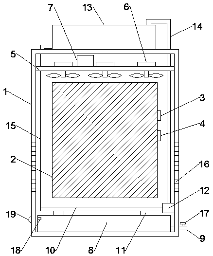
Figure 1 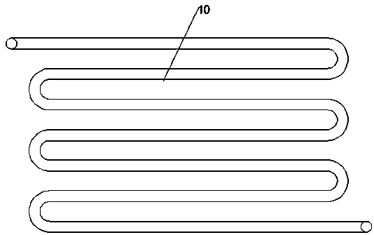
Figure 2
Abstract
Description
technical field
[0001] The invention relates to the technical field of PLC control boxes, in particular to a PLC control box with good heat dissipation and dehumidification performance. Background technique
[0002] The full English name of PLC is Programmable Logic Controller, an electronic system operated by digital operations, designed for use in industrial environments. It uses a type of programmable memory for its internal storage program, execution of user-oriented instructions such as logic operations, sequence control, timing, counting and arithmetic operations, and controls various types of machinery through digital or analog input / output Or production process, is the core part of industrial control. However, a large amount of heat will be generated during the working process of the PLC. The current heat dissipation method generally has the problem of low heat dissipation efficiency, and long-term high temperature affects the service life of the PLC. The patent No...
Examples
Embodiment 1
[0021] Such as Figure 1-2 As shown, the PLC control box with good heat dissipation and dehumidification performance according to the embodiment of the present invention includes a housing 1, and a PLC controller 2 is arranged in the middle position inside the housing 1, and one side of the PLC controller 2 is respectively A temperature sensor 3 and a humidity sensor 4 are arranged in sequence, a support frame 5 is provided on the top inside of the housing 1, a number of cooling fans 6 are provided on the top of the support frame 5, and a side of the top of the support frame 5 is provided with Microcontroller 7, the bottom end inside the housing 1 is provided with a water collection tank 8, the bottom end of one side of the water collection tank 8 is provided with a drain pipe 9 inserted through the housing 1, the water collection tank 8 The top is provided with a condensing pipe 10 at the bottom of the PLC controller 2, and the condensing pipe 10 is fixedly connected to the w...
Embodiment 2
[0026] Such as Figure 1-2 As shown, the bottom ends on both sides of the housing 1 are respectively provided with a number of cooling holes 16, the drain pipe 9 is provided with a valve 17, and the top of the inner side of the water collection tank 8 is provided with a liquid level sensor 18, The bottom end of one side of the housing 1 is provided with a warning light 19 electrically connected to the liquid level sensor 18, the condensation pipe 10 is made of aluminum, and the condensation pipe 10 is a rotary structure. In addition, the warning light 19 is the sound and light alarm lamp.
[0027] from figure 1 It can be seen from the figure that the bottom ends on both sides of the housing 1 are respectively provided with a number of cooling holes 16, the drain pipe 9 is provided with a valve 17, and the top of the inner side of the water collection tank 8 is provided with a liquid level sensor. 18. The bottom end of one side of the housing 1 is provided with an alarm lamp ...