
Combined high-speed electroplating shielding device
A technology of high-speed electroplating and shielding device, applied in the direction of electrolysis process, electrolysis components, etc., can solve the problems of non-adjustable width of polygonal tubular body shielding device, high current density at both edges of cathode strip, dense power lines at both edges of cathode, etc. Uniform current density distribution, favorable for uniform distribution and small voltage loss
Patent Information
- Authority / Receiving Office
- CN · China
- Patent Type
- Applications(China)
- Current Assignee / Owner
- Publication Date
- 2020-06-19
- Estimated Expiration
- Not applicable · inactive patent
Smart Images
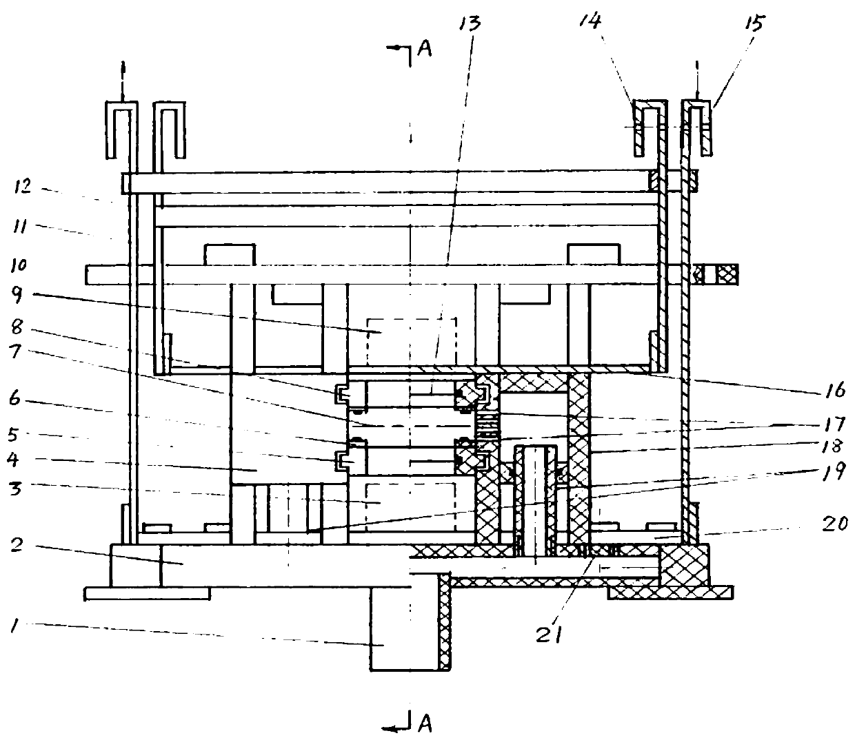
Figure 1 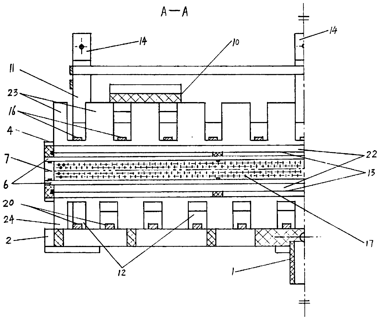
Figure 2
Abstract
Description
technical field
[0001] The invention relates to the technical field of high-speed electroplating, in particular to a combined high-speed electroplating shielding device. Background technique
[0002] High-speed electroplating is an electroplating method that uses a special device to obtain a good coating even when using a very high cathode current density. High-speed electroplating has been widely used in industrial fields such as machinery and electronics. In high-speed electroplating, in order to increase the cathode current density without reducing the cathode current efficiency and prevent the coating from burning, the electroplating solution and the plating piece are often made to move quickly relative to each other. The high-speed electroplating of IC lead frame-like metal strip adopts the method of horizontal moving continuous electroplating, and the cathode of the metal strip passes continuously in the working tank. The high-speed electroplating tank is divided int...
Examples
Embodiment Construction
[0032] The following will clearly and completely describe the technical solutions in the embodiments of the present invention with reference to the accompanying drawings in the embodiments of the present invention. Obviously, the described embodiments are only some, not all, embodiments of the present invention.
[0033] In describing the present invention, it is to be understood that the terms "center", "middle", "longitudinal", "transverse", "length", "width", "thickness", "upper", "lower", " Front, Back, Left, Right, Parallel, Horizontal, Top, Both Ends, Vertical, Bottom, Inner, Inner, Outer ” and other indicated orientations or positional relationships are based on the orientations or positional relationships shown in the accompanying drawings, which are only for the convenience of describing the present invention and simplifying the description, rather than indicating or implying that the referred device or part must have a specific orientation, with a specific configurat...