
Control system for hydraulic energy intelligent storage and precise transfer device
A transfer device and control system technology, applied in the field of hydraulic energy intelligent storage and precise transfer device control system, to achieve the effect of promoting the liquid discharge process and improving energy consumption
Patent Information
- Authority / Receiving Office
- CN · China
- Current Assignee / Owner
- Publication Date
- 2020-10-13
Smart Images
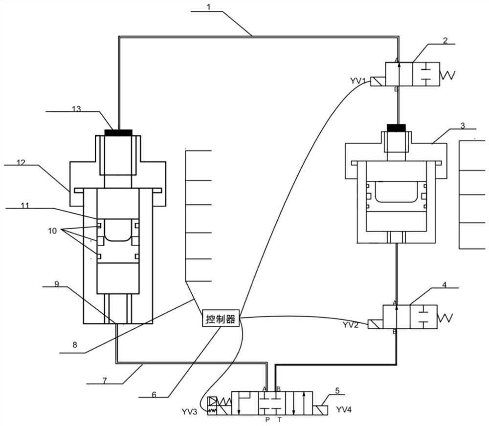
Figure 1 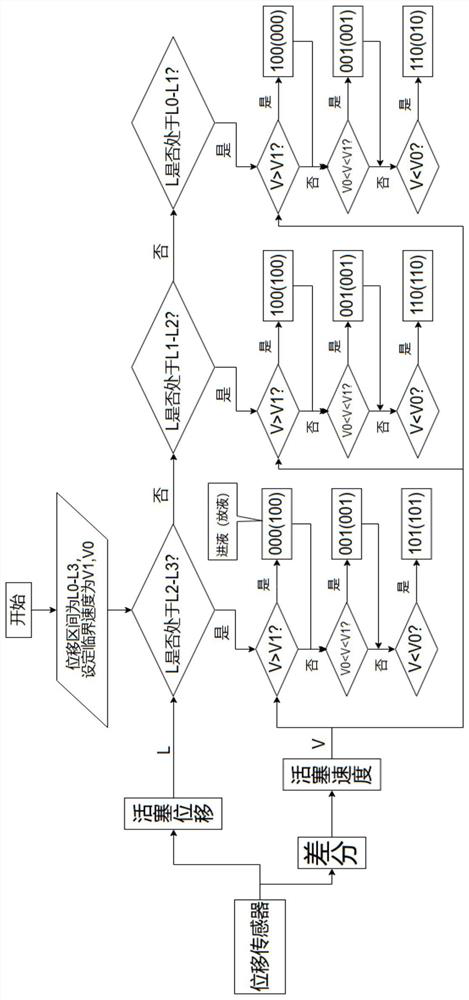
Figure 2
Abstract
Description
technical field
[0001] The invention relates to a hydraulic energy storage device, in particular to a hydraulic energy intelligent storage and precise transmission device control system. By detecting the piston displacement and piston speed of the energy storage device, the energy storage capacity and output capacity of the accumulator can be adjusted, which can be used in various controllable hydraulic energy storage devices, such as hydraulic machines, fine blanking machine tools, etc. Background technique
[0002] The traditional hydraulic system can be divided into two categories: hydraulic transmission system and hydraulic control system. The main function of the hydraulic transmission system is to transmit power and motion, while the hydraulic control system must make the output of the hydraulic system meet specific performance requirements. The biggest problem facing the current hydraulic system is the problem of energy utilization. Due to the particularity of the hyd...
Examples
Embodiment Construction
[0021] specific implementation
[0022] The present invention will be further described below in conjunction with the accompanying drawings and embodiments.
[0023]The hydraulic energy intelligent storage and precise transmission device control system implemented according to the present invention includes a main accumulator 12, an air cavity pressure regulator 3, a high-speed gas switching valve 2, a high-speed liquid switching valve 4, and a three-position four-way solenoid valve 5 , Gas connection pipe 1, oil connection pipe 7, displacement sensor 8, PLC controller 6. The gas interface 13 of the main accumulator 12 is connected to the gas interface of the gas cavity pressure regulator 3 through the gas connection pipe 1. The gas connection pipe 1 is divided into two sections, and a high-speed gas switching valve 2 is connected in series in the middle. The liquid interface of the main accumulator 12 communicates with the A interface of the three-position four-way solenoid ...