
Vibration-assisted nano rolling device
A vibrating device and rolling technology, applied in the field of hot embossing, can solve the problems of obstructing ultrasonic waves, low filling rate, pattern damage accuracy, etc., and achieve the effects of improving filling degree, uniform force and eliminating air bubbles.
Patent Information
- Authority / Receiving Office
- CN · China
- Current Assignee / Owner
- Publication Date
- 2021-01-12
Smart Images
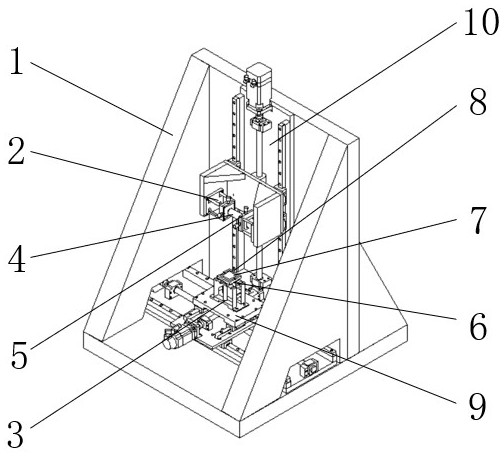
Figure 1 
Figure 2 
Figure 3
Abstract
Description
technical field
[0001] The invention relates to the field of thermal embossing, in particular to a vibration-assisted nano-rolling device. Background technique
[0002] Nanoimprint technology has the advantages of low cost, high resolution, and mass production, and is widely used in optical lenses, self-cleaning, and microelectronics manufacturing processes. It has attracted the general attention and research enthusiasm of researchers in the industry. MIT Technology Review will It is listed as one of the top ten emerging technologies that will change the world. However, the finished imprinted products now have defects such as low filling rate, pattern damage and poor precision. In order to solve these defects, researchers shifted their research field to ultrasonic vibration-assisted imprinting.
[0003] In the patent with the publication number CN 102336016 A, the Japanese scholar H. Mekaru and the Korean scholar Hyun Woo Yu all proposed the method of ultrasonic assisted im...
Examples
Embodiment Construction
[0027] like figure 1 As shown, the vibration-assisted nano-rolling device includes a frame 1, a four-column connecting frame 2, a Z-direction vibration device 3, an embossing device 4, a fine-tuning device 5, a heating device 6, and a substrate chuck 7 , Cooling device 8, X-Y axis displacement platform 9, Z-axis displacement platform 10, wherein frame 1 is placed horizontally on the horizontal plane, Z-axis displacement platform 10 and X-Y axis displacement platform 9 are fixed on the frame 1 by screws, and the four-column connecting frame 2 is fixed on the Z-axis displacement platform 10 by screws, the imprinting device 4 is fixed on the four-column connecting frame 2 by screws, the Z-direction vibration device 3 is fixed on the X-Y axis displacement platform 9 by screws, and the heating device 6 is fixed on the Z-axis by screws. On the vibration device 3, the substrate chuck 7 is fixed on the heating device 6 by screws, the height of the placed substrate is higher than the d...