
Side suspension type supporting device for traction motor test
A side-suspended, support device technology, applied in the direction of motor generator testing, measuring device casings, etc., can solve the problems of bulkiness, large test support device, poor versatility, etc.
Patent Information
- Authority / Receiving Office
- CN · China
- Current Assignee / Owner
- Publication Date
- 2021-05-04
Smart Images
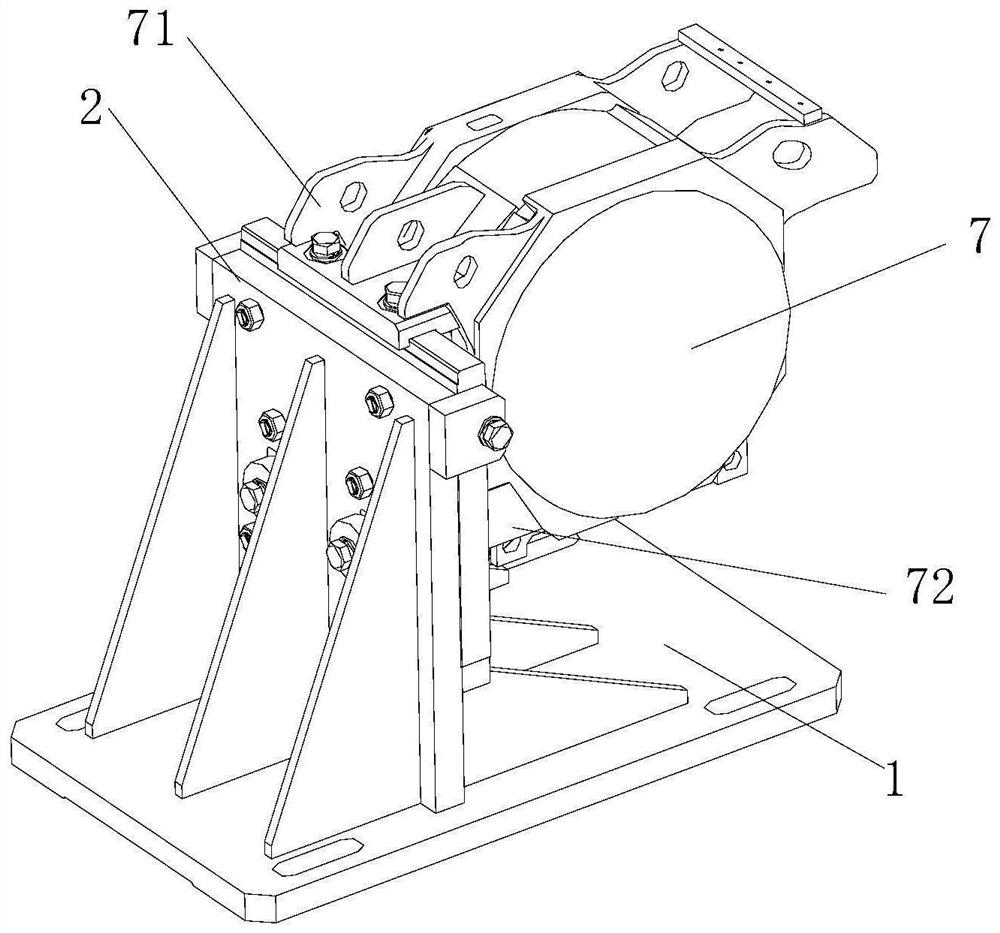
Figure 1 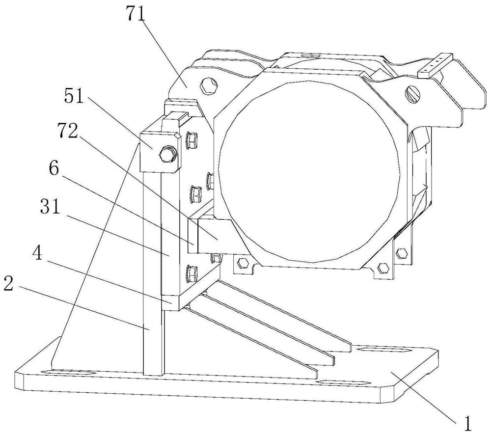
Figure 2 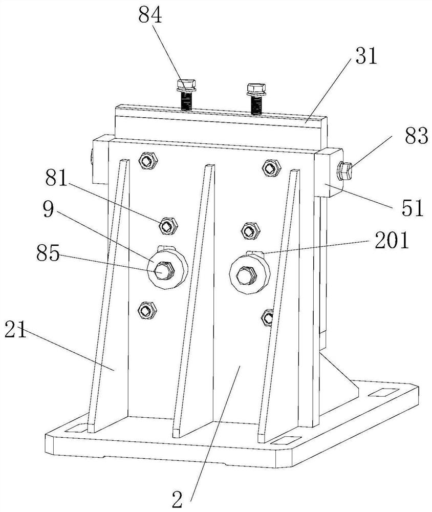
Figure 3
Abstract
Description
Technical field
[0001] The present invention relates to a traction motor testing apparatus, and more particularly to a diagonal support device for traction motor test.Background technique
[0002] The installation method is more common in the side-type rotary electric machine, and the side suspension traction motor side is suspended by the mounting of the motor, and the upper suspension motor is welded and the motor is suspended and the motor is passed. Suspension and lower suspension are fixed on other devices. In general, different series of different types of motors are suspended, the relative position between the lower suspension is different, in addition, due to the high center of the dynamic rotating shaft connected to the motor rotation axis due to the test Specific, when the motor is mounted on the test support device, it is necessary to ensure that the motor rotor center is high with the center of the test drag rotary shaft center, and the above factors lead to test support for d...
Examples
Embodiment Construction
[0025]The present invention will be further described in detail below with reference to the accompanying drawings and specific embodiments.
[0026]Such asFigure 1 to 4As shown, the traction motor test side suspension supporting means for the present embodiment, including the base 1, the frame 2, and the movable block 31, and the frame 2 is fixed to the base 1, and the movable block 31 is secured vertically through the first fastener. On the frame 2, the movable block 31 is remote from the side of the frame 2 to mount the motor, and the frame 2 is provided with a beam 4, and the upper end of the movable block 31 projects out of the rack 2, and the lower end is abutting on the beam 4, movable block 31 Between the beam 4, by the second fastener, the frame 2 is provided with a side stop 51 on both sides of the movable block 31, and the side stopper 51 is connected between the side stopper 51 and the movable blocks 31. 31 is located on one side of the frame 2, a block 6 is provided, and wh...