
An improved motor rotor
An improved technology for motor rotors, applied in the direction of electromechanical devices, electrical components, electric components, etc., can solve the problems of difficult disassembly and reinstallation, affecting the normal operation of the motor, permanent magnet disassembly cannot be disassembled at the same time, and achieves the convenience of later maintenance Effect
Patent Information
- Authority / Receiving Office
- CN · China
- Patent Type
- Patents(China)
- Current Assignee / Owner
- Publication Date
- 2022-05-03
Smart Images
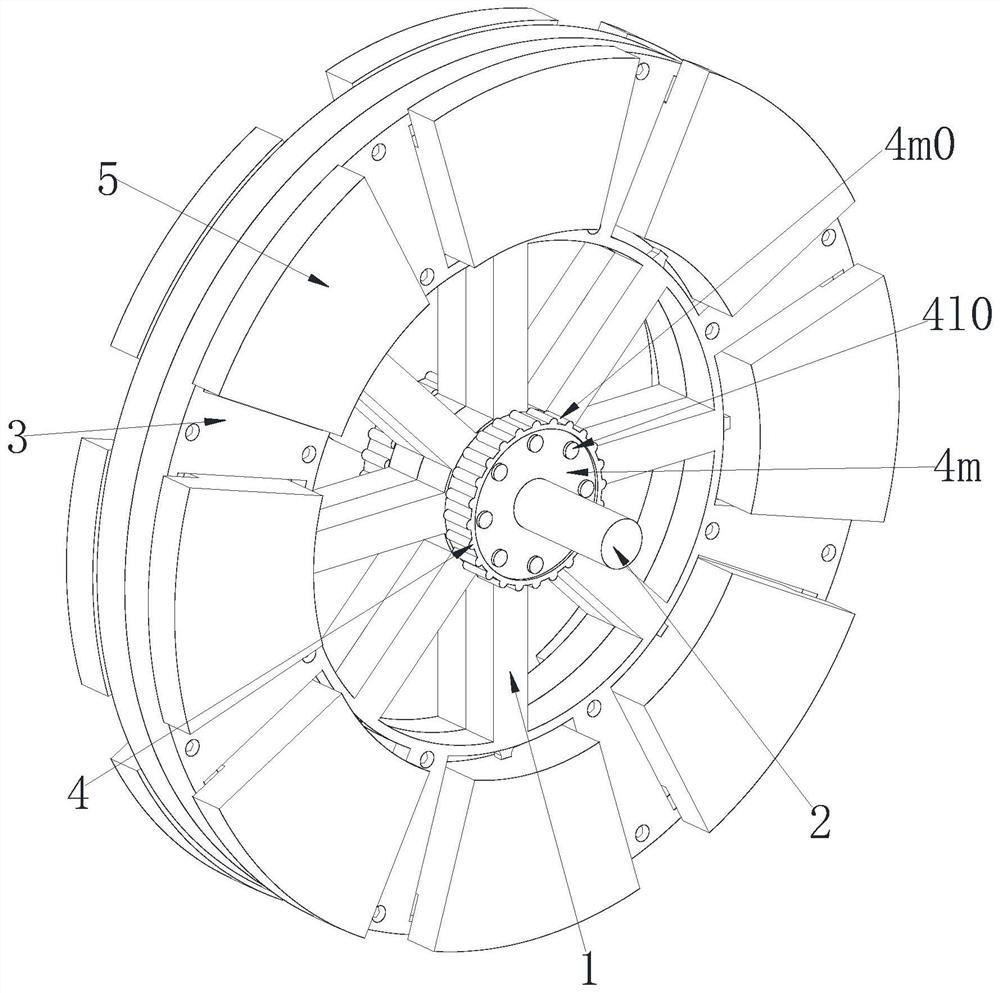
Figure 1 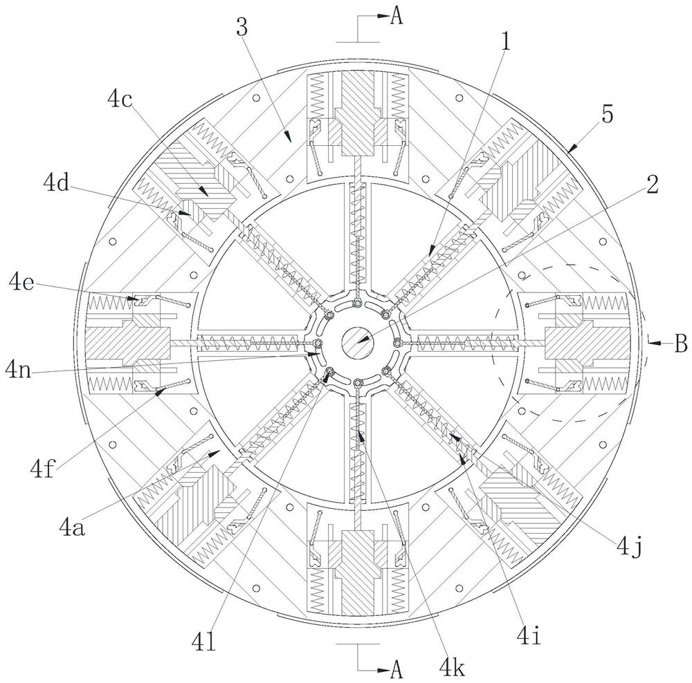
Figure 2 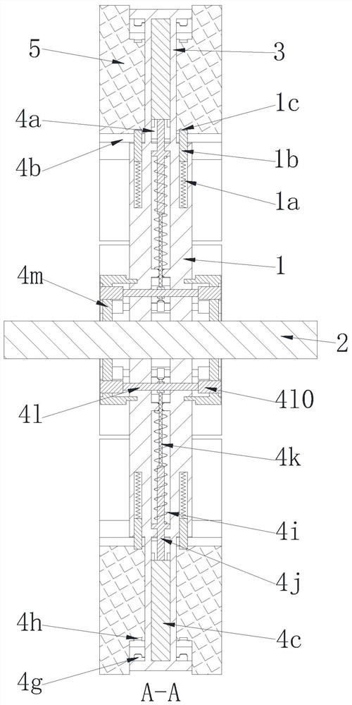
Figure 3
Abstract
Description
technical field
[0001] The invention relates to the field of motor rotor design, in particular to an improved motor rotor. Background technique
[0002] The motor rotor is also the rotating part in the motor. The motor consists of two parts, the rotor and the stator. It is used to realize the conversion device of electrical energy and mechanical energy and mechanical energy and electrical energy. The rotor of the motor is divided into two types: the inner rotor rotation mode and the outer rotor rotation mode; The core body is a rotating body, which can output torque (referring to the motor) or receive energy (referring to the generator). The rotation mode of the outer rotor is to use the outer body of the motor as the rotating body. Different methods facilitate the application in various occasions. The present invention is aimed at the design of the rotor of a disc motor. Generally, the rotor and stator of a motor are fitted inside and outside. In order to make the disc mot...
Examples
Embodiment Construction
[0029] In order to make the technical means realized by the present invention, creative features, goals and effects easy to understand, the following combination Figure 1 to Figure 6 , to further elaborate the present invention.
[0030] An improved motor rotor, including a rotor bracket 1, a rotating shaft 2, a rotor yoke 3, an installation unit 4 and a permanent magnet 5, two rotor brackets 1 are symmetrically arranged and connected by bolts, and the two A rotating shaft 2 is fixedly installed in the middle of the rotor bracket 1, and a rotor yoke 3 is fixedly installed on the outer edge of the rotor bracket 1. Several installation units 4 are jointly arranged on the rotor bracket 1 and the rotor yoke 3 along the circumferential direction thereof, and each installation unit 4 is symmetrically installed with a permanent magnet 5; wherein:
[0031] The installation unit 4 includes an installation cavity 4a, an installation groove 4b, an installation top block 4c, an installa...