
Vehicle-mounted spare tire storage rack
A storage rack and vehicle-mounted technology, which is applied in the layout of spare tires, vehicle components, transportation and packaging, etc., can solve the problems of inability to meet the general design requirements of spare tire mounting brackets, poor versatility, and uneven stress on the spare tire.
Patent Information
- Authority / Receiving Office
- CN · China
- Patent Type
- Applications(China)
- Current Assignee / Owner
- Publication Date
- 2022-01-04
- Estimated Expiration
- Not applicable · inactive patent
Smart Images
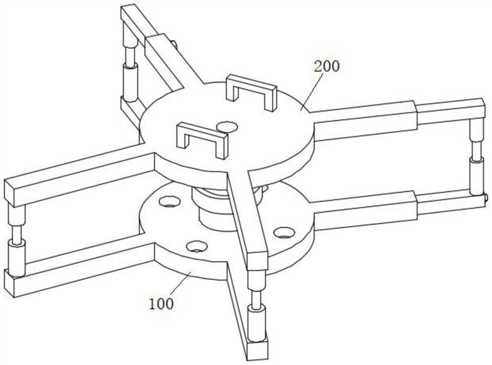
Figure 1 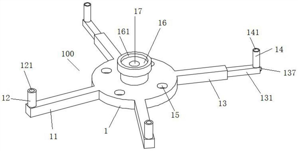
Figure 2 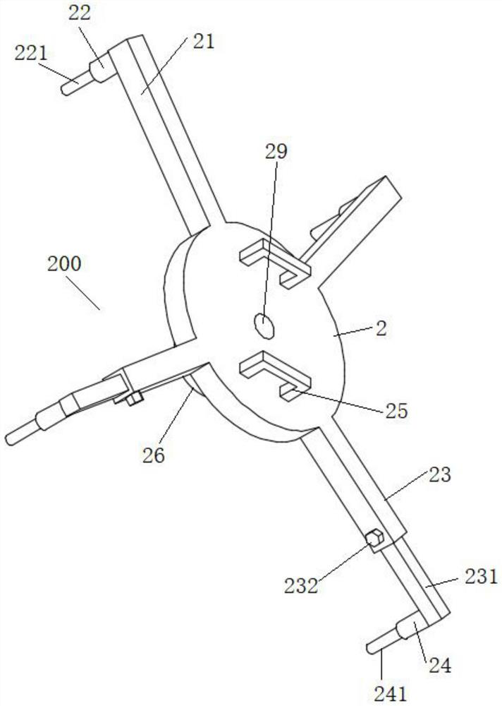
Figure 3
Abstract
Description
technical field
[0001] The invention belongs to the technical field of automobile parts, in particular to a storage rack for a vehicle spare tire. Background technique
[0002] In the related art, the spare tire support is a cross-shaped support structure, and the spare tire is placed on the cross-shaped support structure. The product quality of the spare tire mounting mechanism with this structure is often difficult to guarantee, especially the main struts, auxiliary struts and support plates of the spare tire bracket often have excessive contact with the rim during the process of compressing the spare tire, causing the rim to be squeezed and damaged. damage problem.
[0003] Secondly, installing the spare tire through the spare tire bracket also has potential risks caused by uneven stress on the spare tire. Not only that, the versatility of the traditional spare tire mounting mechanism is poor, and there are fewer tire models that can be matched by a spare tire rack; the...
Examples
Embodiment Construction
[0027] The following will clearly and completely describe the technical solutions in the embodiments of the present invention with reference to the accompanying drawings in the embodiments of the present invention. Obviously, the described embodiments are only some, not all, embodiments of the present invention. Based on the embodiments of the present invention, all other embodiments obtained by persons of ordinary skill in the art without creative efforts fall within the protection scope of the present invention.
[0028] In describing the present invention, it is to be understood that the terms "opening", "upper", "lower", "thickness", "top", "middle", "length", "inner", "surrounding" etc. Indicating orientation or positional relationship is only for the convenience of describing the present invention and simplifying the description, and does not indicate or imply that the components or elements referred to must have a specific orientation, be constructed and operated in a sp...