
Full-automatic three-generation hub bearing vibration measuring instrument and measuring method
A wheel bearing and vibration measurement technology, which is applied in the direction of measuring devices, measuring ultrasonic/sonic/infrasonic waves, instruments, etc., can solve the problems of inconvenient pressing automatic detection, unfavorable detection and production work, inconvenient and efficient buffer control of wheel bearing vibration measuring instruments, etc. Achieve the effect of convenient lighting operation, convenient limit extrusion work, and convenient inspection of fine positions
Patent Information
- Authority / Receiving Office
- CN · China
- Patent Type
- Applications(China)
- Current Assignee / Owner
- Publication Date
- 2022-07-12
Smart Images
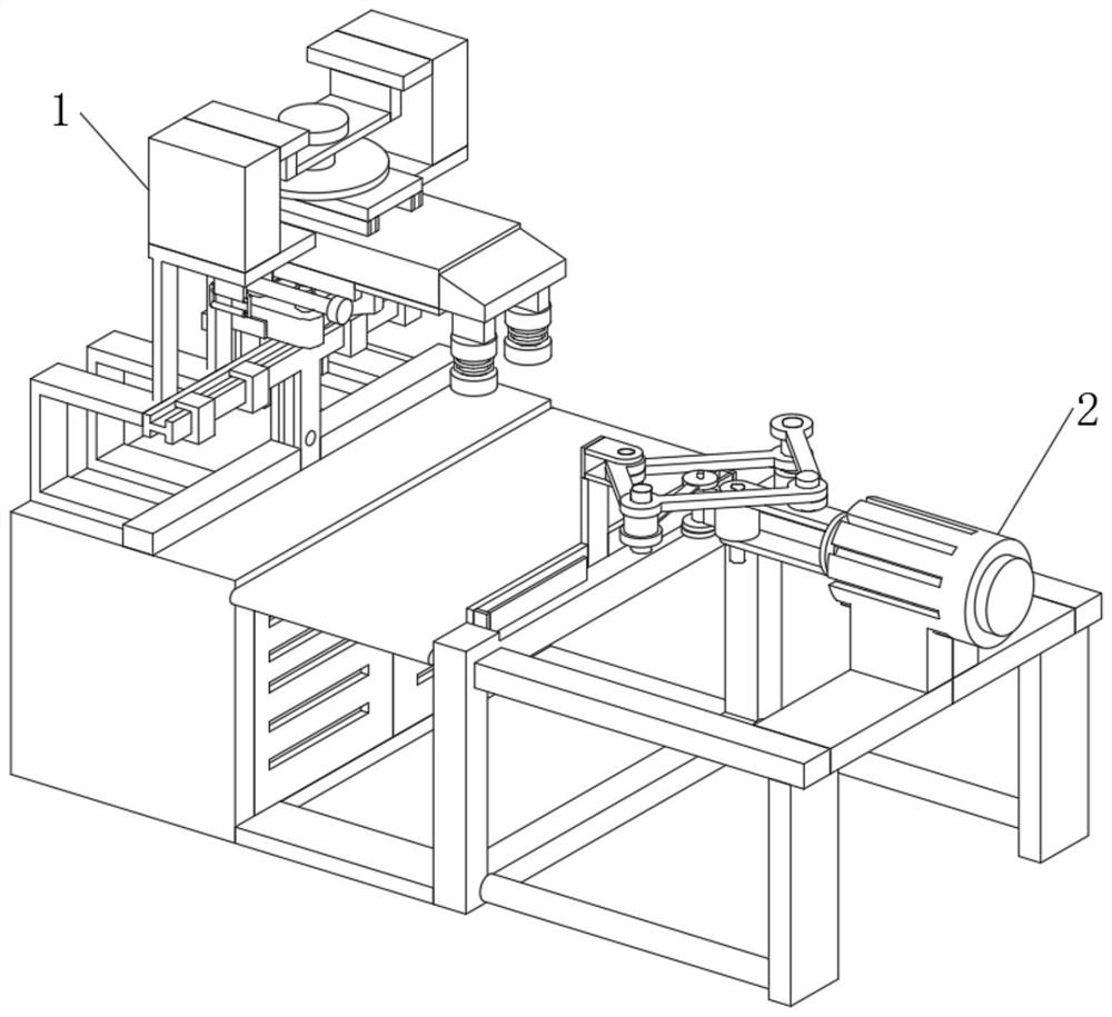
Figure 1 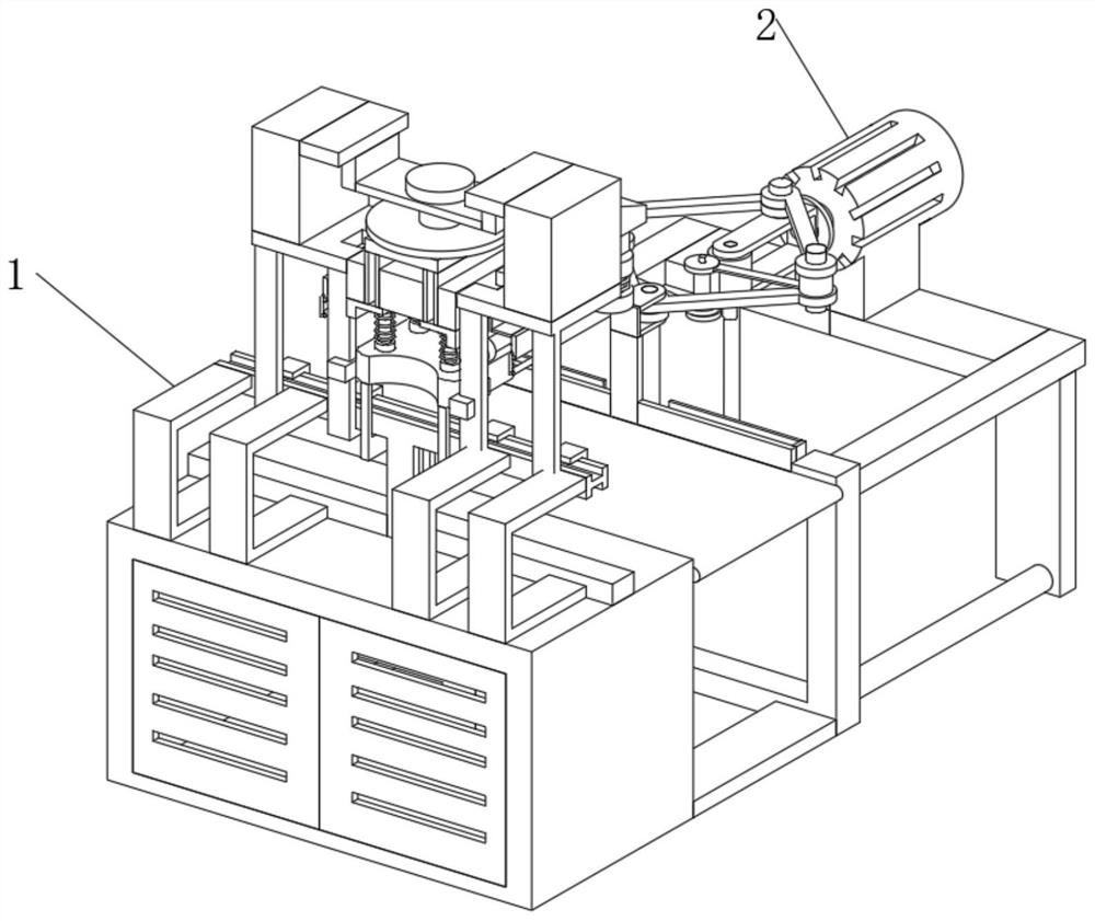
Figure 2 
Figure 3
Abstract
Description
technical field
[0001] The invention relates to the technical field of bearing vibration measuring instrument equipment, in particular to a fully automatic third-generation wheel hub bearing vibration measuring instrument and a measuring method. Background technique
[0002] Bearing vibration measuring instrument is a special instrument for measuring the vibration speed of deep groove ball bearings, angular contact ball bearings and tapered roller bearings. It adopts high-precision air-floating spindle as the measurement benchmark, the basic vibration of the instrument is low, and advanced data acquisition and data processing are adopted. Computers are suitable for bearing vibration detection by bearing manufacturers, bearing application companies such as motor factories and commodity inspection departments for bearing acceptance, and also for bearing vibration analysis in universities and scientific research institutions.
[0003] According to the Chinese Patent No. CN20191...
Examples
Embodiment 1
[0041] see figure 1 , figure 2 , image 3 , an embodiment provided by the present invention: a fully automatic third-generation wheel hub bearing vibration measuring instrument, comprising a vibration detection structure 1 and a pressing connection structure 2, and the side end position of the vibration detection structure 1 is fixedly connected with the pressing connection structure 2. ;
[0042] see Figure 4 , the vibration detection structure 1 includes a buffer platen 3, a spring ring frame 4, a side vertical rod frame 5, a central spring rod 6, an elastic contact frame 7 and a vibration detection sensor 8, and the side vertical rod frame 5 is arranged in the vibration detection structure 1. At the top position of the end, a spring ring frame 4 is elastically connected at the central position of the side pole frame 5, and the bottom end position of the spring ring frame 4 is fixedly connected with the buffer table 3, and the front end position of the buffer table 3 is...
Embodiment 2
[0049] On the basis of Example 1, as Figure 8 As shown, the upper part of the front end of the vibration detection structure 1 is fixedly connected with a support mounting bracket 25 , the side end of the support mounting bracket 25 is connected with a communication seat frame 24 , and the lower end of the communication seat frame 24 is installed with a lighting fixture 23 .
[0050] In the implementation of this embodiment, the user can connect with the outside world by installing the lighting fixture 23, the communication seat 24, and the support mounting bracket 25, and the lighting fixture 23, the communication seat 24, and the support mounting bracket 25 can be connected to the outside world. It is driven by external electric energy, realizes the work, facilitates the lighting operation, better conducts the close observation work of the inspection personnel, and facilitates the inspection of the fine position.
[0051] A measurement method of an automatic third-generatio...