
Motor control unit and electric power steering apparatus using the same and vehicle
a technology of motor control unit and electric power steering apparatus, which is applied in the direction of electronic commutators, dynamo-electric converter control, dynamo-electric gear control, etc., can solve the problems of not being able to provide the steering angle sensor, so as to improve the reliability of the vehicle
Patent Information
- Authority / Receiving Office
- US · United States
- Patent Type
- Patents(United States)
- Current Assignee / Owner
- Publication Date
- 2018-08-21
Smart Images
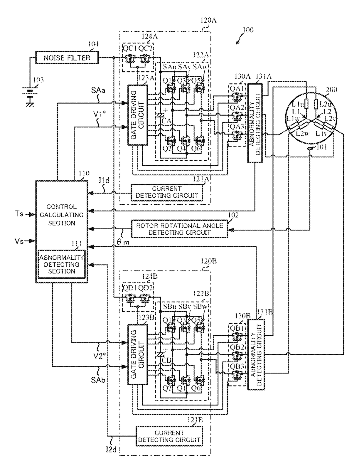
Figure 1 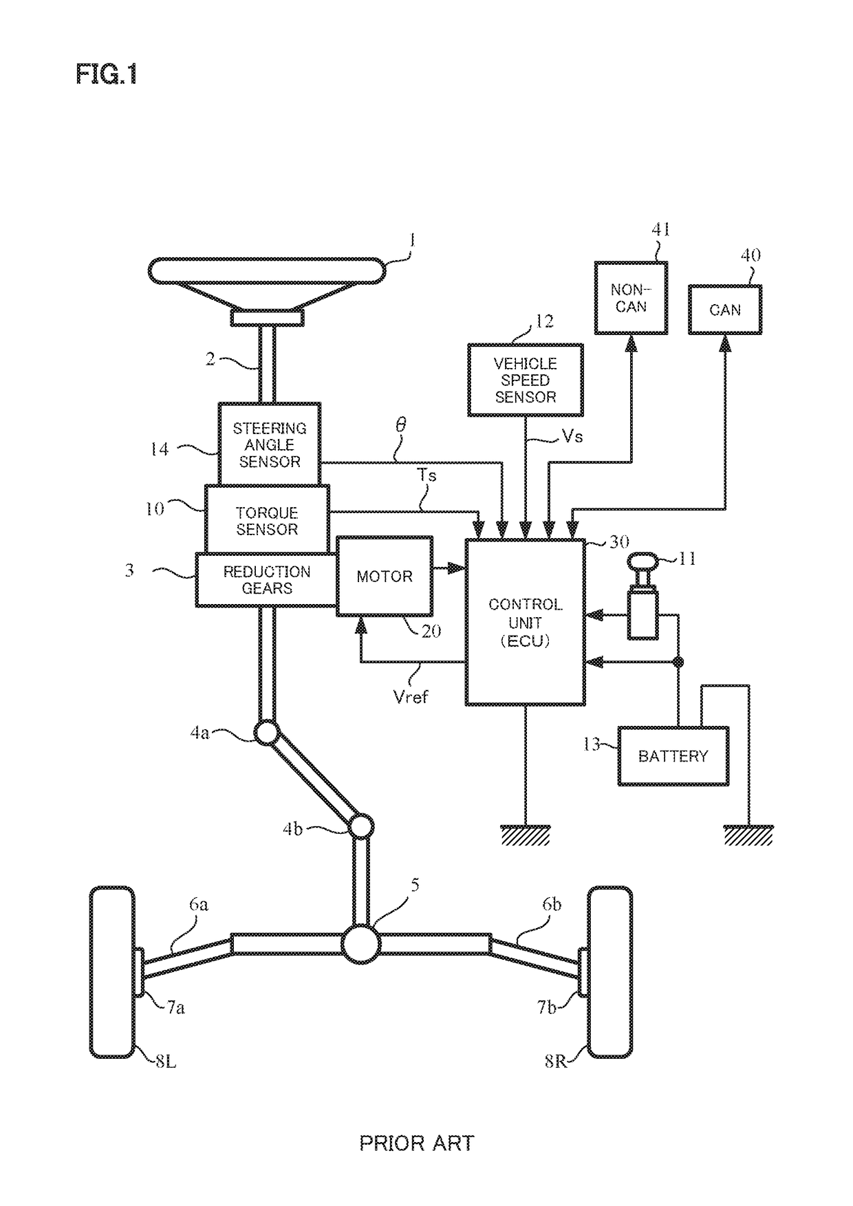
Figure 2 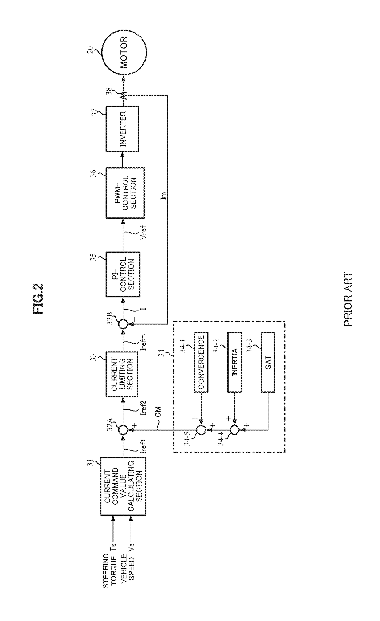
Figure 3
Abstract
Description
CROSS REFERENCE TO RELATED APPLICATIONS
[0001] This application is a National Stage of International Application No. PCT / JP2015 / 069982, filed on Jul. 13, 2015, which claims priority from Japanese Patent Application No. 2014-144107, filed on Jul. 14, 2014, the contents of all of which are incorporated herein by reference in their entirety.TECHNICAL FIELD
[0002] The present invention relates to a motor control unit that controls a motor having multi-system motor windings by means of a 3-phase current feedback system provided with a current control section through a motor driving circuit of each winding system and to an electric power steering apparatus using the same and a vehicle, and in particular to the motor control unit that has a function that changes by switching parameters of the current control section corresponding to a driving system number of multi-system motor windings, wherein a noisy sound and a vibration are not generated even if the system is switched, and to the electric...
Examples
Embodiment Construction
[0029]First, an example of a 2-system winding motor will be explained with reference to FIGS. 3 and 4. Although the present invention relates to an electric motor, the following explanations merely describes as a “motor”.
[0030]A 3-phase motor 200 has two triangle-formed winding arrangements as shown in FIG. 3, and has an SPM motor constitution comprising of a stator having teeth T which are magnetic poles forming slots projected to an inside direction of inner peripheral surface and an 8-poles surface magnet-type rotor 12R which is rotatable, wherein permanent magnets PM are disposed on the surface opposite to the teeth T at inside side of the stator 12S. Here, the number of teeth T of the stator 12S is set as “phase number×2n (“n” is an integer equal to or more than 2)”, for example, this embodiment is a constitution of 8-poles and 12-slots by setting “n=2”.
[0031]Then, with 2-systems as shown in FIG. 4, a first 3-phase motor winding L1 and a second 3-phase motor winding L2 correspo...