

Cylinder head structure for internal combustion engine and internal combustion engine
a technology of internal combustion engine and cylinder head, which is applied in the direction of machines/engines, valve drives, mechanical equipment, etc., can solve the problems of thermal deformation inside the cam carrier, the relative displacement between the cylinder head and the cam carrier occurs, and the surface damage of the fretting, so as to reduce the relative position and relative angle between the camshaft and the cam bearing, inhibit the wear or seize of the cam bearing
Patent Information
- Authority / Receiving Office
- US · United States
- Patent Type
- Patents(United States)
- Current Assignee / Owner
- Publication Date
- 2020-06-23
Smart Images
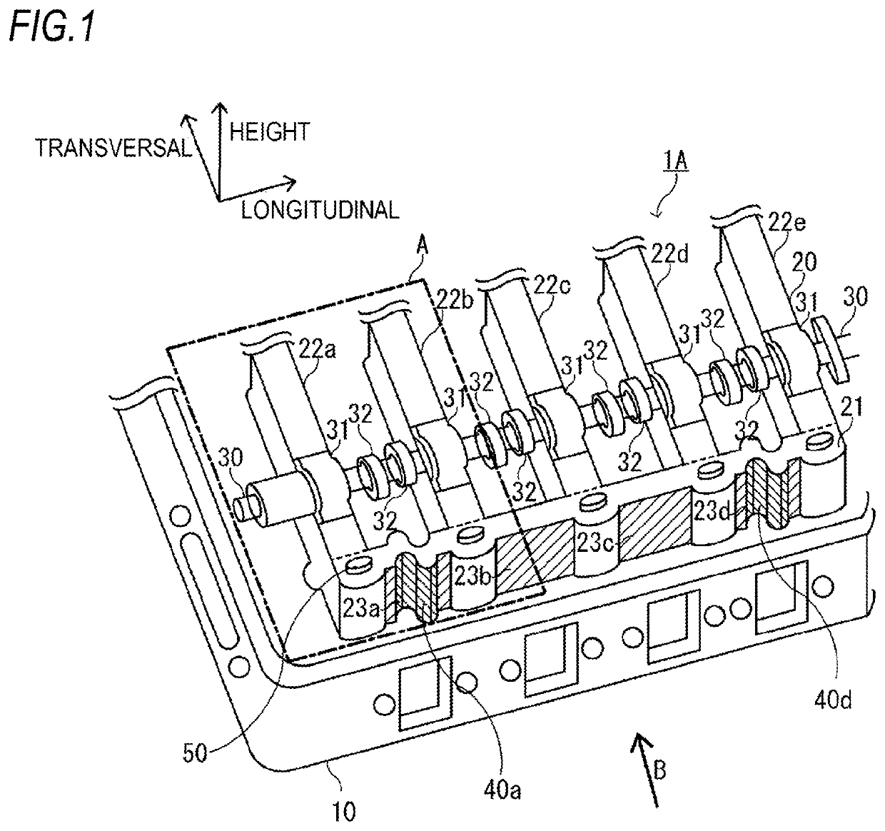
Figure 1 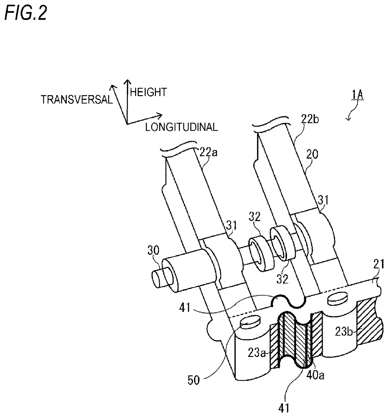
Figure 2 
Figure 3
Abstract
Description
CROSS-REFERENCE TO RELATED APPLICATIONS
[0001] This application is a U.S. National Stage entry of PCT Application No: PCT / JP2016 / 082563 filed Nov. 2, 2016, which claims priority to Japanese Patent Application No. 2015-219400, filed Nov. 9, 2015, the contents of which are incorporated herein by reference.TECHNICAL FIELD
[0002] The present disclosure relates to a cylinder head structure for an internal combustion engine and an internal combustion engine, in which a monolithic cam carrier is placed on a top of a cylinder head.BACKGROUND ART
[0003] In general, most of internal combustion engines, such as diesel engines, are configured as a multi-cylinder engine provided with a plurality of cylinders. In a case where an OHC (overhead cam carrier) is employed for a valve mechanism in the multi-cylinder engine, multi-cylinder engine includes a camshaft having a plurality of cams for opening and closing an intake valve and an exhaust valve arranged on an upper portion of the inside of each cylind...
Examples
first embodiment
[0029]A cylinder head structure 1A for an internal combustion engine according to the present disclosure is a structure in which a monolithic cam carrier 20 is placed on the top of a cylinder head 10 and then is fixed thereto by bolts 50 as shown in FIG. 1.
[0030]Also, in the cylinder head structure 1 for the internal combustion engine, the cam carrier 20 includes a pair of longitudinal frames 21 provided parallel to an axial direction (longitudinal direction) of a camshaft 30 and a plurality of transversal frames 22 (22a, 22b, 22c, 22d, 22e) connected to the pair of longitudinal frames 21 to be spaced from each other and supporting the camshaft 30 via cam bearings 31.
[0031]Herein, directions as shown in FIG. 1 will be described. A longitudinal direction is a longitudinal direction of the cylinder head 20 and is the same as an axial direction of the camshaft 30. Also, this direction is the same as an axial direction of the cam bearings 31 arranged on the respective transversal frames...