
Fence support
a technology of fence support and construction method, which is applied in the direction of construction, pasturing equipment, building types, etc., can solve the problems of time-consuming and labor-intensive process, lack of aesthetic appeal of insulators and rods, and inconvenient construction of fence support, etc., to achieve cost-effective and less time-consuming, simple process, and improve aesthetics
Patent Information
- Authority / Receiving Office
- US · United States
- Patent Type
- Applications(United States)
- Current Assignee / Owner
- Publication Date
- 2002-09-12
- Estimated Expiration
- Not applicable · inactive patent
Smart Images
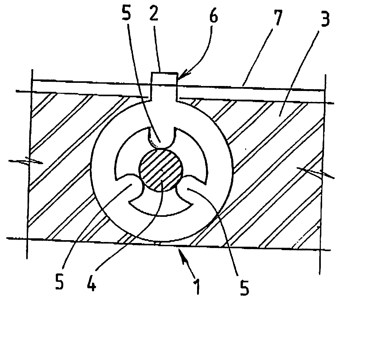
Figure 1 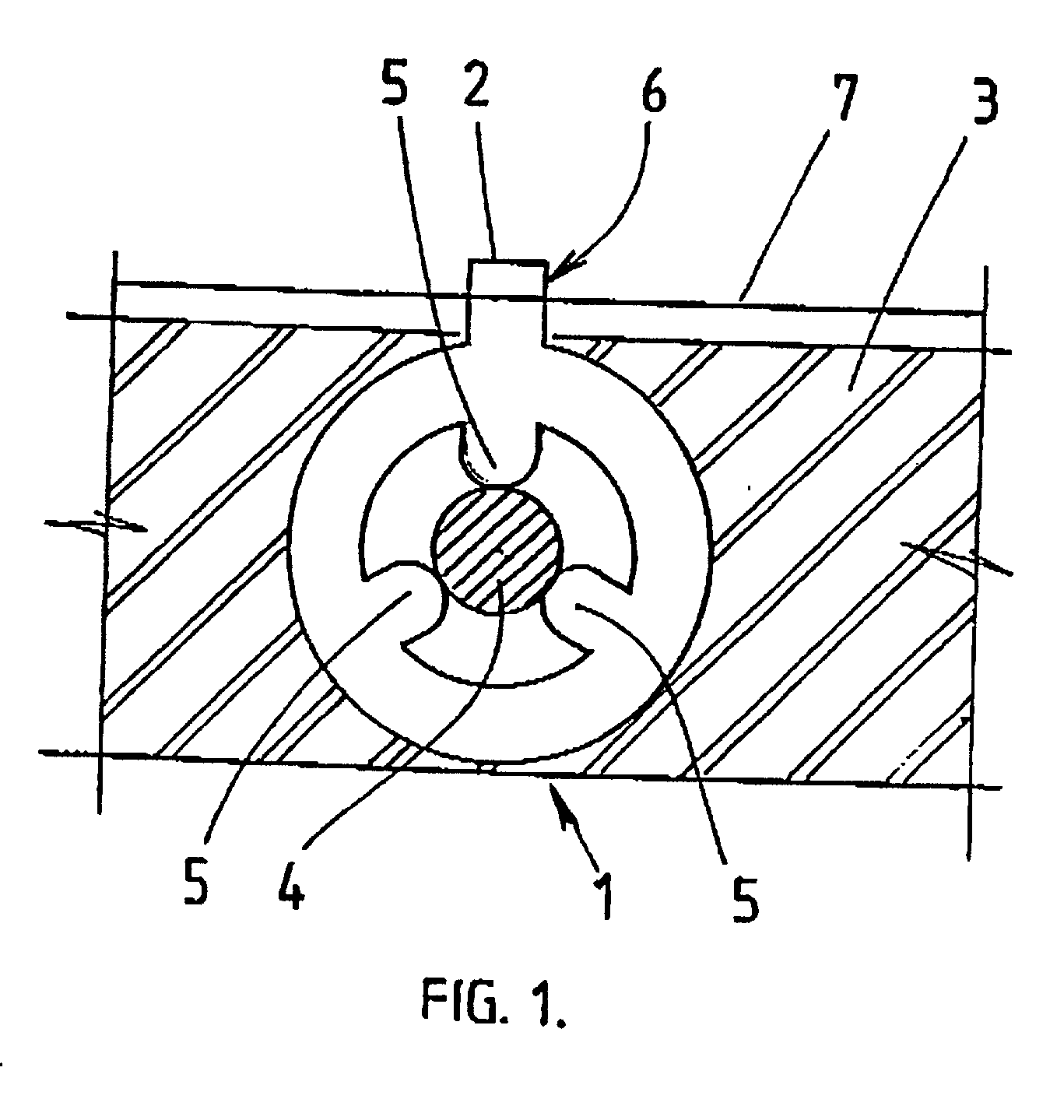
Figure 2 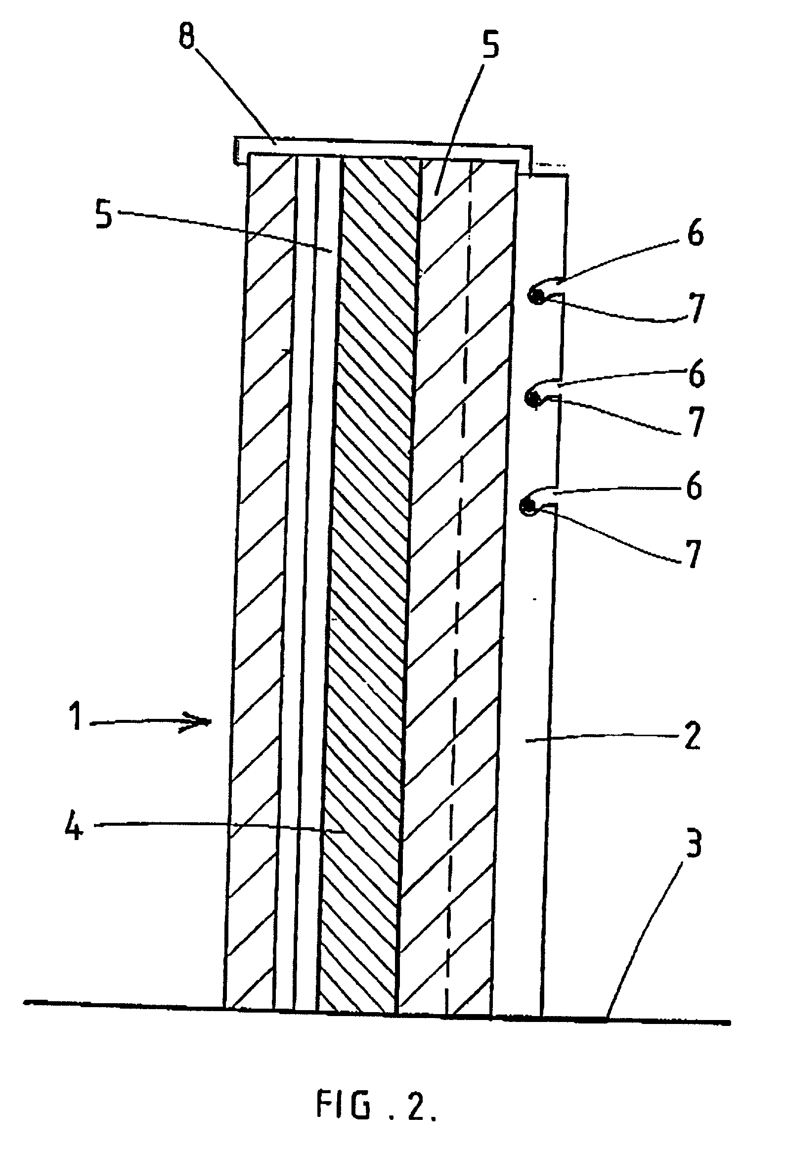
Figure 3
Abstract
Description
[0001] This invention relates to an improved fence support.
[0002] Reference throughout this specification shall be mainly made to use of the present invention for use with electrified fences. However, it should be seen that the present invention can have application to non-electrified fences as well.
[0003] Insulators for wires conducting an electrical current are sometimes manufactured separately from the main support wire, and attached to the support as required.
[0004] Security systems employing wall-top fencing are usually installed by attaching insulators to support rods atop the wall.
[0005] This process can be labour intensive and time consuming. Further, the insulators and the rods often lack aesthetic appeal.
[0006] The aesthetic quality of the insulators is important as wall-top security fencing is commonly employed in the domestic market. Thus, the main support for the insulator and electric fence needs to be configured for both appearance and its ability to support and insul...
Examples
Embodiment Construction
[0063] According to FIG. 1 there is shown a plan view of one embodiment of the present invention.
[0064] The sleeve (1) is substantially cylindrical, but includes a web (2) formed on the exterior of the cylindrical section. The sleeve (1) is mounted a top a wall (3), and has been slid over a rod (4) which is in turn embedded or otherwise fixably attached to the walltop (3).
[0065] It is envisaged that the sleeve (1) may be hammered or forced over the rod (4), to provide a tight friction fit.
[0066] In order to allow for variable rod diameters, projections (5) are formed on the inside of the sleeve projecting towards the centre. These projections (5) may be deformable to a degree. to provide a tight friction fit between the projections and the rod (4) whilst the deformability allows for variations in rod diameter.
[0067] The web (2) includes incisions, indicated by arrow 6 along the length of the web. the incisions configured to receive electric fence wire length (7).
[0068] The sleeve (1...