
System for injecting fuel into a turbomachine
a turbomachine and fuel injection technology, which is applied in the direction of liquid fuel engines, instruments, machine control, etc., can solve the problems of non-uniform fuel injection into the combustion chamber, non-uniform metering valve opening and closing after a delay, and the turbomachine lighting is not uniform, so as to reduce the non-uniform rate, simplify the hydraulic circuit, and mitigate the drawbacks.
Patent Information
- Authority / Receiving Office
- US · United States
- Patent Type
- Applications(United States)
- Current Assignee / Owner
- Publication Date
- 2003-05-22
- Estimated Expiration
- Not applicable · inactive patent
Smart Images
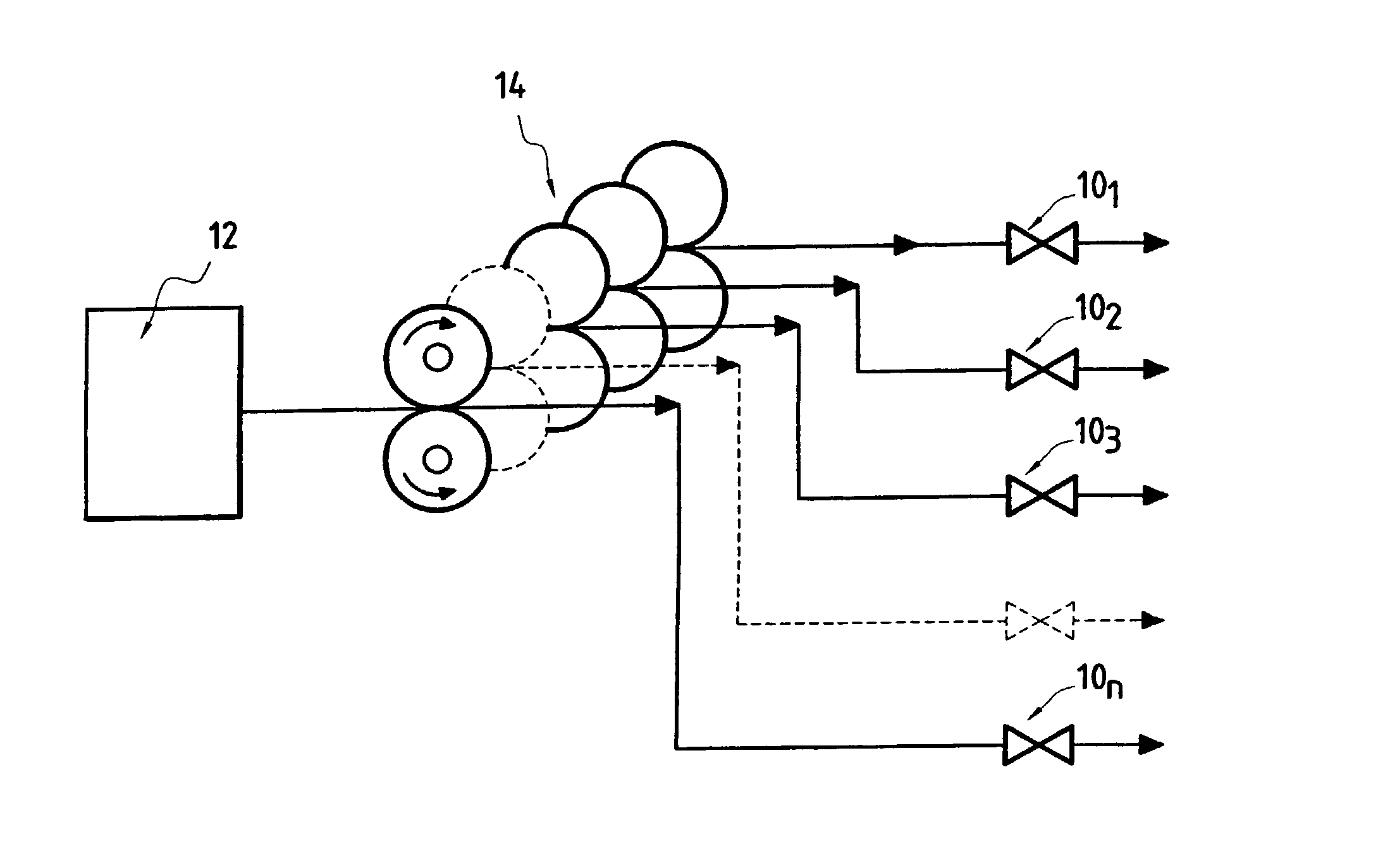
Figure 1 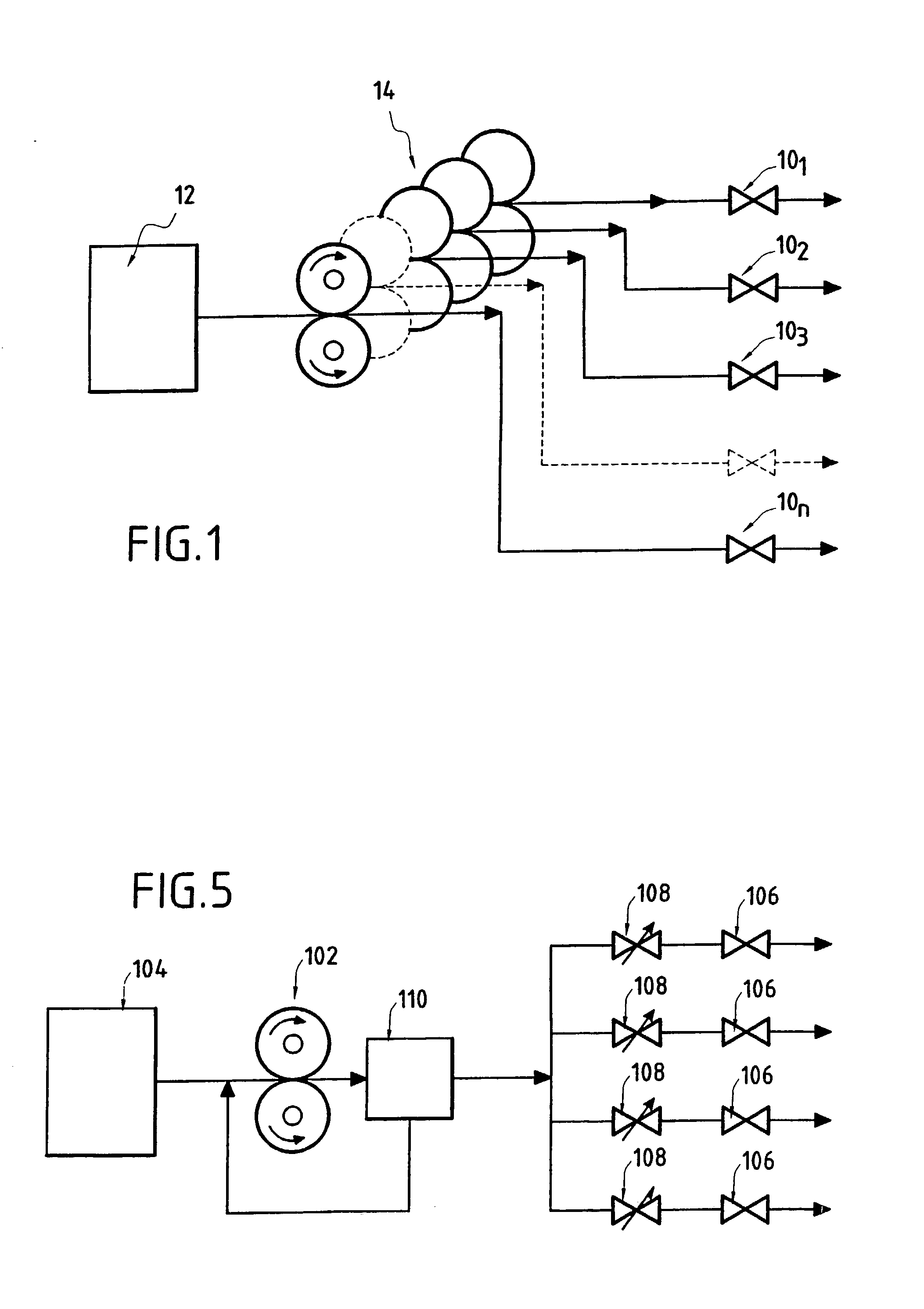
Figure 2 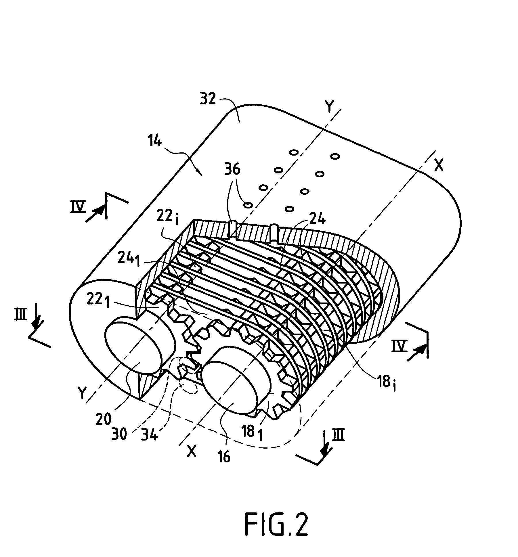
Figure 3
Abstract
Description
Background of the invention
[0001] The present invention relates to the general field of systems for injecting fuel into a combustion chamber in a turbomachine. It relates more particularly to fuel pump means fitted to such injection systems.
[0002] As shown diagrammatically in FIG. 5, a system for injecting fuel into a turbomachine typically comprises: a pump 102, e.g. a gear pump, driven by a motor (not shown) enabling fuel to be taken from a fuel tank 104; a plurality of injectors 106 placed in a combustion chamber of the turbomachine and each provided with a fuel metering valve 108; and a fuel metering device 110 interposed between these two sets of elements in order to control the rate at which fuel is to flow from the pump to the injectors. The excess fuel coming from the metering device 110 is reinjected to the inlet of the pump 102.
[0003] With such a configuration, the rate at which fuel is injected into the combustion chamber of the turbomachine depends in particular on the s...
Examples
Embodiment Construction
[0016] Reference is made initially to FIG. 1 which is a diagram showing the hydraulic circuit of the fuel injection system of the invention.
[0017] In this figure, there can be seen a system for injecting fuel into a turbomachine having N injectors 10 to 10.sub.N (only four are shown in FIG. 1) disposed in a combustion chamber (not shown) of the turbomachine. The injectors 10.sub.1 to 10.sub.N are fed with fuel from a fuel tank 12. A single pumping means 14 is interposed between the N injectors 10.sub.1 to 10.sub.N and the fuel tank 12 so as to take fuel from the tank and deliver fuel to the injectors in N metered flows that are preferably all at the same rate. In a single action, the single pumping means 14 serves both to pump the fuel from the tank and to deliver the fuel as pumped in this way to the N injectors. The fuel is also delivered in such a manner as to meter the N flow rates delivered to the injectors 10.sub.1 to 10.sub.N.
[0018] FIGS. 2 to 4 show the single pumping means ...