
Tape winding method
a winding method and tape technology, applied in the direction of carrier storage means, record carrier guidance, thin material handling, etc., can solve the problem of difficult winding disturban
Patent Information
- Authority / Receiving Office
- US · United States
- Patent Type
- Applications(United States)
- Current Assignee / Owner
- Publication Date
- 2005-02-03
- Estimated Expiration
- Not applicable · inactive patent
Smart Images
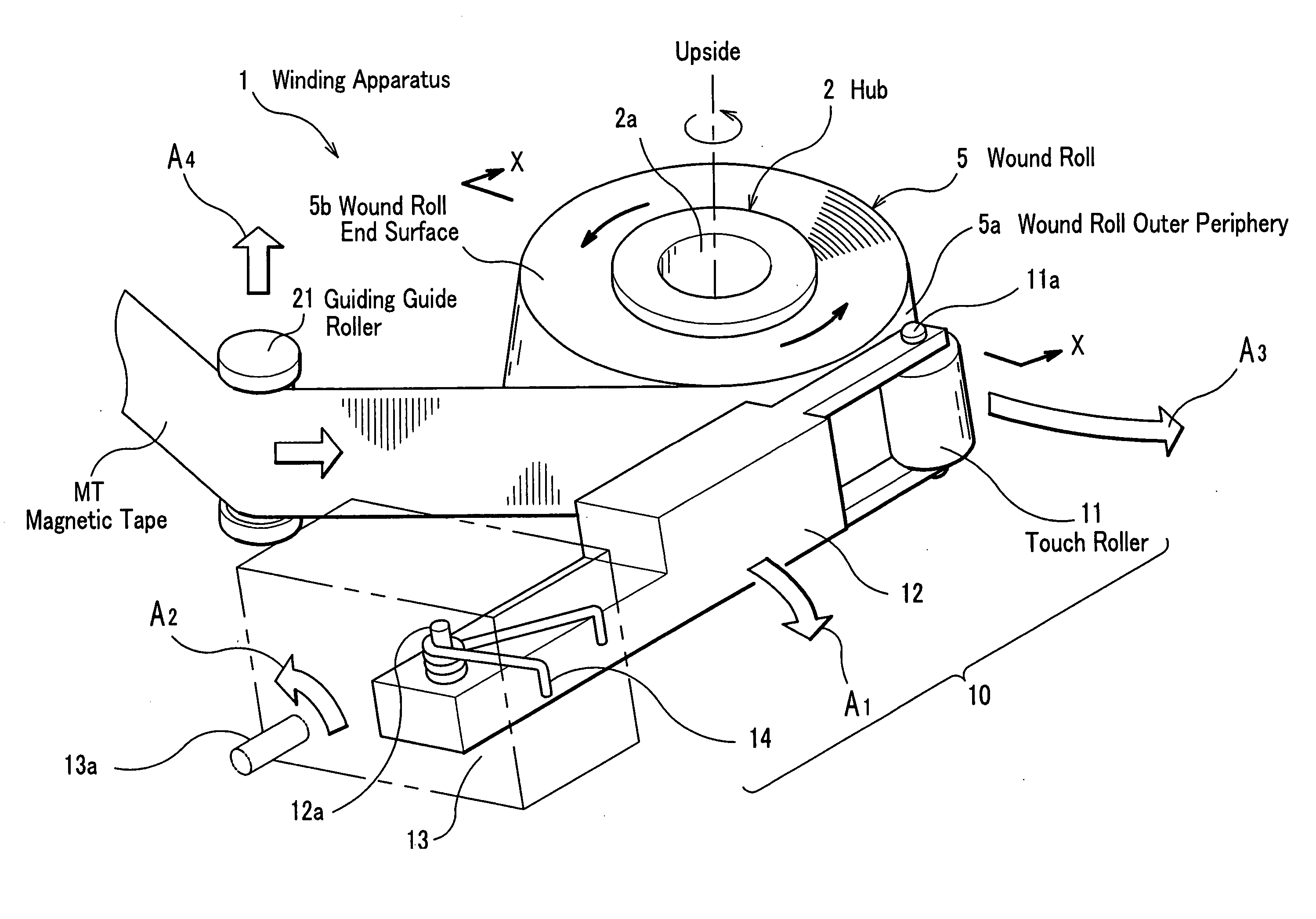
Figure 1 
Figure 2 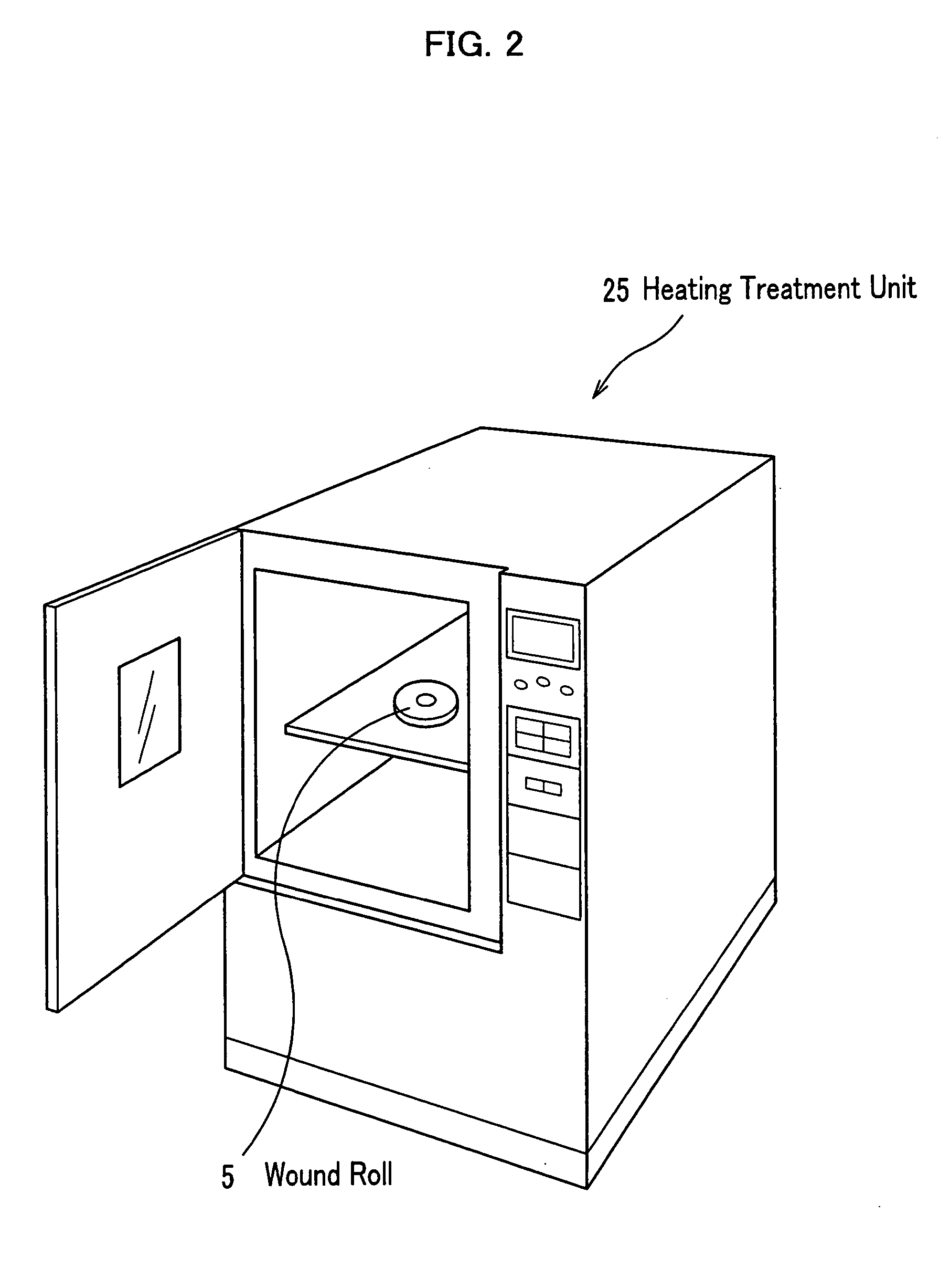
Figure 3
Abstract
Description
BACKGROUND OF THE INVENTION
[0001] 1. Field of the Invention
[0002] The present invention relates to a tape winding method.
[0003] 2. Description of the Related Art
[0004] In magnetic recording tape (hereinafter abbreviated to “magnetic tape”) layer thinning and surface smoothing progress, based upon a high recording density. However, in winding such the magnetic tape on a tape reel by a tape winder, a tape drive, and the like a winding disturbance is easy to occur, and particularly, in high speed winding a remarkable winding disturbance often occurs.
[0005] Such the winding disturbance of the magnetic tape wound on the tape reel is easy to give damage during transportation, thereby a bad winding way is given during storage, and a running accuracy within the tape drive results in being aggravated and causes an abnormal tracking, so it is a problem.
[0006] Therefore, it is an important program in assuring requirement performances of a commercial product to ensure a quality of a wound...
Examples
first embodiment
[0045] A tape winding method related to a first embodiment of the present invention will be described, referring to FIGS. 1 to 6.
[0046] Meanwhile, in the first embodiment, as shown in FIG. 1, an axial direction of a hub 2 is made an up / down direction, one end side thereof (upside shown inFIG. 1) is set the upside, the other end side (see FIGS. 3A, 3B, and the like) is set a downside, and magnetic tape MT is assumed to be wound on the hub 2 so that a wound roll end surface 5b at the upside of a wound roll 5 becomes concave. A touch roller 11 is also assumed to be same as above.
[0047] First, a configuration of a winding apparatus will be described, referring to FIG. 1.
[0048] As shown in FIG. 1, a winding apparatus 1 has the hub 2 for winding the magnetic tape MT and the touch roller 11, and is configured by comprising: a wound roll outer surface push means 10 for pushing a wound roll outer periphery 5a (tape surface of an outmost periphery), which is a periphery of the wound roll 5...
second embodiment
[0101] Subsequently, a tape winding method related to a second embodiment of the present invention will be described, referring to FIGS. 7, 8A, and 8B as needed.
[0102] The tape winding method related to the second embodiment is different in nothing but a winding process, compared to the tape winding method related to the first embodiment. In more detail, are different a configuration of a winding apparatus and a method for winding the magnetic tape MT on the hub 2. In the first embodiment the magnetic tape MT is wound and the touch roller 11 is moved like an arc; whereas, in the second embodiment the magnetic tape MT is wound while the hub 2 is moved like an arc for a touch roller 33 at a fixed position.
[0103] First, the configuration of the winding apparatus, which is used in the tape winding method related to the second embodiment, will be described, and then, the winding process by the winding apparatus will be described.
[0104] As shown in FIG. 7, a winding apparatus 30 relate...
third embodiment
[0113] Subsequently, a tape winding method related to a third embodiment of the present invention will be described, referring to FIGS. 9A and 9B.
[0114] The tape winding method related to the third embodiment is different in nothing but a winding process, compared to the tape winding method related to the first embodiment. In more detail, are different a configuration of a winding apparatus and a method for winding the magnetic tape MT on the hub 2. The third embodiment does not use the wound roll outer periphery push means 10 related to the first embodiment, attaches a winding guide 51 having a guide surface 51a to an upside end surface of the hub 2, and moves a guiding guide roller 23 to an upside as the magnetic tape MT is wound so that an upper edge of the magnetic tape MT is wound along the guide surface 51a (see an arrow mark A7 in FIG. 9A).
[0115] First, the configuration of the winding apparatus, which is used in the tape winding method related to the third embodiment, will...