
System for ejecting a spin-stabilized space flying body
Patent Information
- Authority / Receiving Office
- US · United States
- Current Assignee / Owner
- Publication Date
- 2005-03-03
- Estimated Expiration
- Not applicable · inactive patent
Smart Images
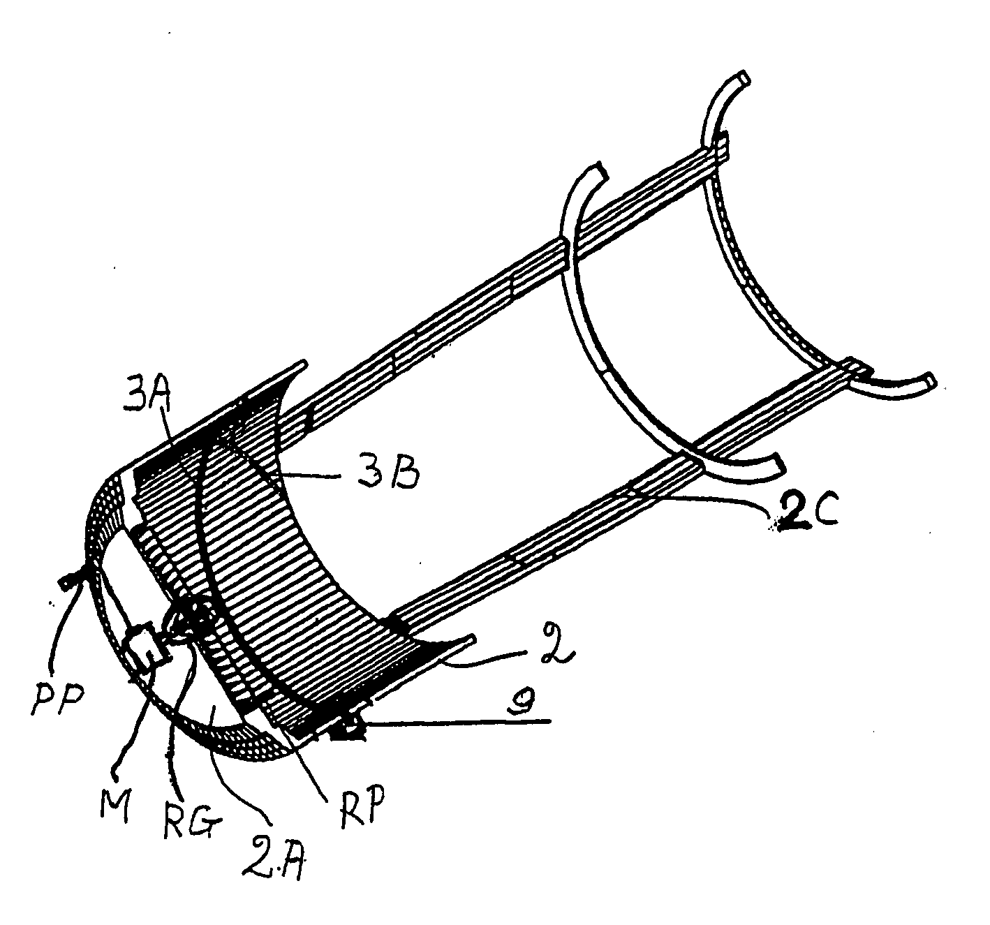
Figure 1 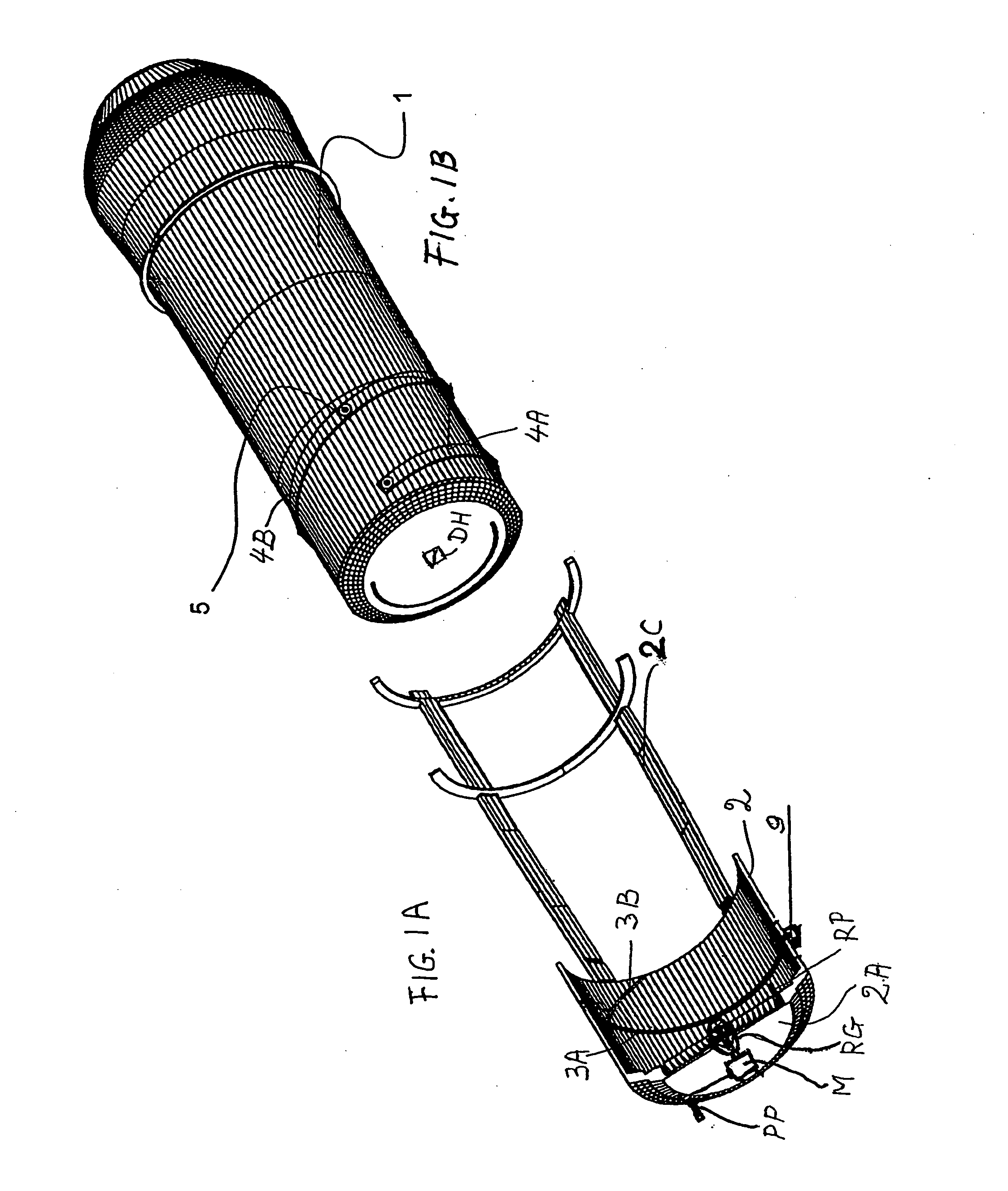
Figure 2 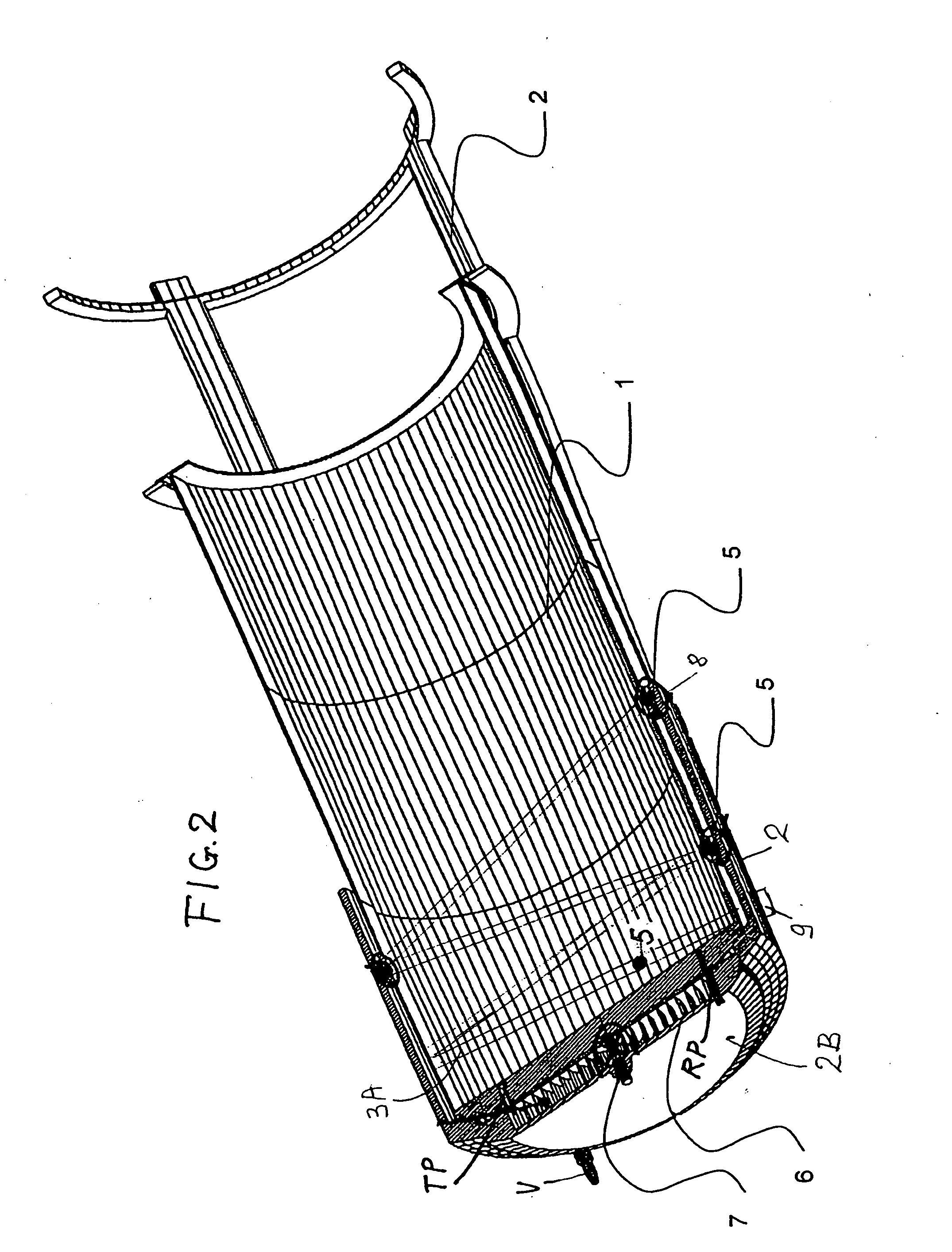
Figure 3
Abstract
Description
PRIORITY CLAIM
[0001] This application is based on and claims the priority under 35 U.S.C. §119 of German Patent Application 103 37 973.8, filed on Aug. 19, 2003, the entire disclosure of which is incorporated herein by reference. FIELD OF THE INVENTION
[0002] The invention relates to launching a spin-stabilized flying body capable of traveling in outer space, either manned or unmanned, either propelled or unpropelled. BACKGROUND INFORMATION
[0003] It is known to eject space flying bodies from a spacecraft, particularly a space station. A drive imposes a driving force on the body to be ejected. The driving force comprises a rotational component for imposing a spin on the flying body as the flying body is ejected and a translatory component for propelling the flying body in a travel direction out of an ejecting tube.
[0004] Heretofore ejecting mechanisms for such flying bodies have been developed for use in satellites, for example in so-called spy satellites for the ejection of retur...
Examples
Embodiment Construction
[0025]FIG. 1A shows an ejection tube 2 with a bottom chamber 2A from which a cover 2B shown in FIG. 2 has been removed. For weight reduction purposes, the ejecting tube is constructed as short as possible. For the same purpose a guide frame 2C is connected to the ejecting tube 2. The ejection tube 2 has an inwardly facing tube wall provided with a guide track or groove section 3A and a further guide track or groove section 3B. The flying body 1 comprises a corresponding first guide track or groove section 4A and a second guide track or groove section 4B. A drive hole DH for engagement by a withdrawable and rotatable drive pin of a motor M or of a reduction gear RG is provided in the bottom of the flying body 1 as shown in FIG. 1B.
[0026] Guide balls or spheres 5 are movable in the guide tracks or grooves 3A, 3B and 4A and 4B. The guide ball 5 in FIG. 1B is shown only for illustration purposes because according to the invention the balls 5 are retained in the ejecting tube 2 as will ...