
Interior permanent magnet motor
a permanent magnet motor and interior technology, applied in the direction of dynamo-electric machines, magnetic circuit rotating parts, magnetic circuit shape/form/construction, etc., can solve problems such as undesirable deviations, and achieve the effect of enhancing the inherent characteristic of interior pm and good tolerance of geometric manufacturing errors
Patent Information
- Authority / Receiving Office
- US · United States
- Patent Type
- Applications(United States)
- Current Assignee / Owner
- Publication Date
- 2019-06-06
Smart Images
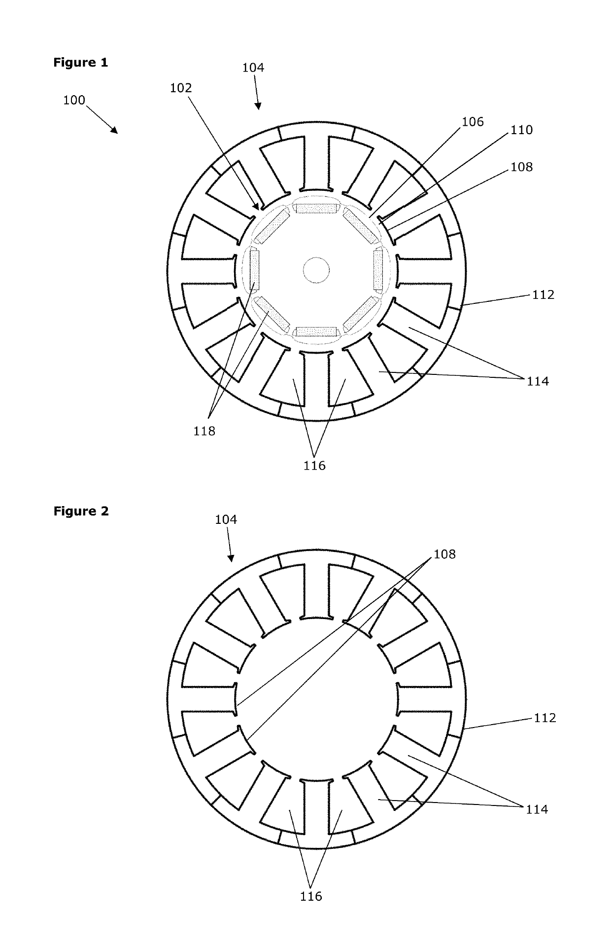
Figure 1 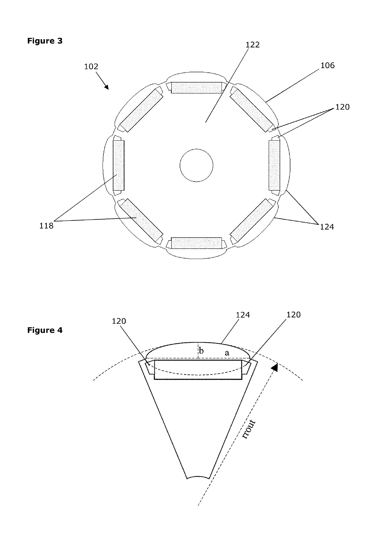
Figure 2 
Figure 3
Abstract
Description
CROSS-REFERENCE TO RELATED APPLICATIONS
[0001] This application claims priority to Great Britain Patent Application No. 1720367.0, filed 6 Dec. 2017, the disclosures of which are incorporated herein by reference in entirety.BACKGROUND TO THE INVENTION
[0002] This invention relates to improvements in electric motors, particularly radial interior permanent magnet motors.
[0003] Interior permanent magnet motors are well known. The basic design of a radial interior permanent magnet motor comprises a stator and a rotor that share a common axis. The stator has a number of stator teeth with the spaces between the teeth defining slots through which a set of stator windings pass as they wind around the teeth. These windings of electrically conductive wire are arranged in multiple electrical phases, typically three phases. The rotor comprises a number of permanent magnets which are located below the surface of the rotor periphery, i.e. interior to the rotor. The magnets alternate around the rotor b...
Examples
Embodiment Construction
[0034]As shown in FIG. 1, an interior permanent magnet (PM) motor 100 comprises a rotor 102 and a stator 104, the rotor 102 having a smaller radius than the stator 104 and the two sharing a common axis of rotation. The rotor 102 defines an outer peripheral face 106 that faces away from the axis of rotation towards a similar, inwardly radially extending face 108 of the stator 104. An air gap 110 is defined between these two faces of the rotor 102 and the stator 104. The stator 104 is fixed in position and the rotor 102 is supported by bearings (not shown) so that it can rotate around the axis when in use.
[0035]The stator 104 comprises a steel support or back iron 112 and is shaped to define a set of 12 inwardly projecting teeth 114, with slots 116 being defined between adjacent teeth 114. A set of windings of copper wire (not shown) are wound through the slots 116 and around the teeth 114 in a defined pattern. The layout of the teeth 114 can be seen clearly in FIG. 2. Note that the e...