
Liquid crystal display device and driving method for the same
Patent Information
- Authority / Receiving Office
- US · United States
- Current Assignee / Owner
- Publication Date
- 2005-12-15
- Estimated Expiration
- Not applicable · inactive patent
Smart Images
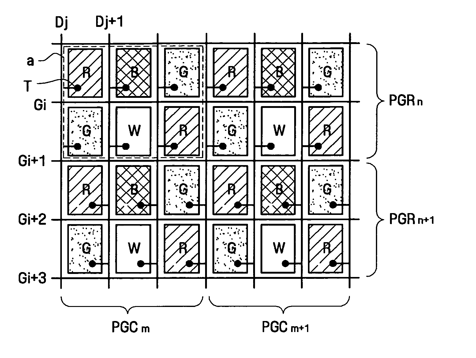
Figure 1 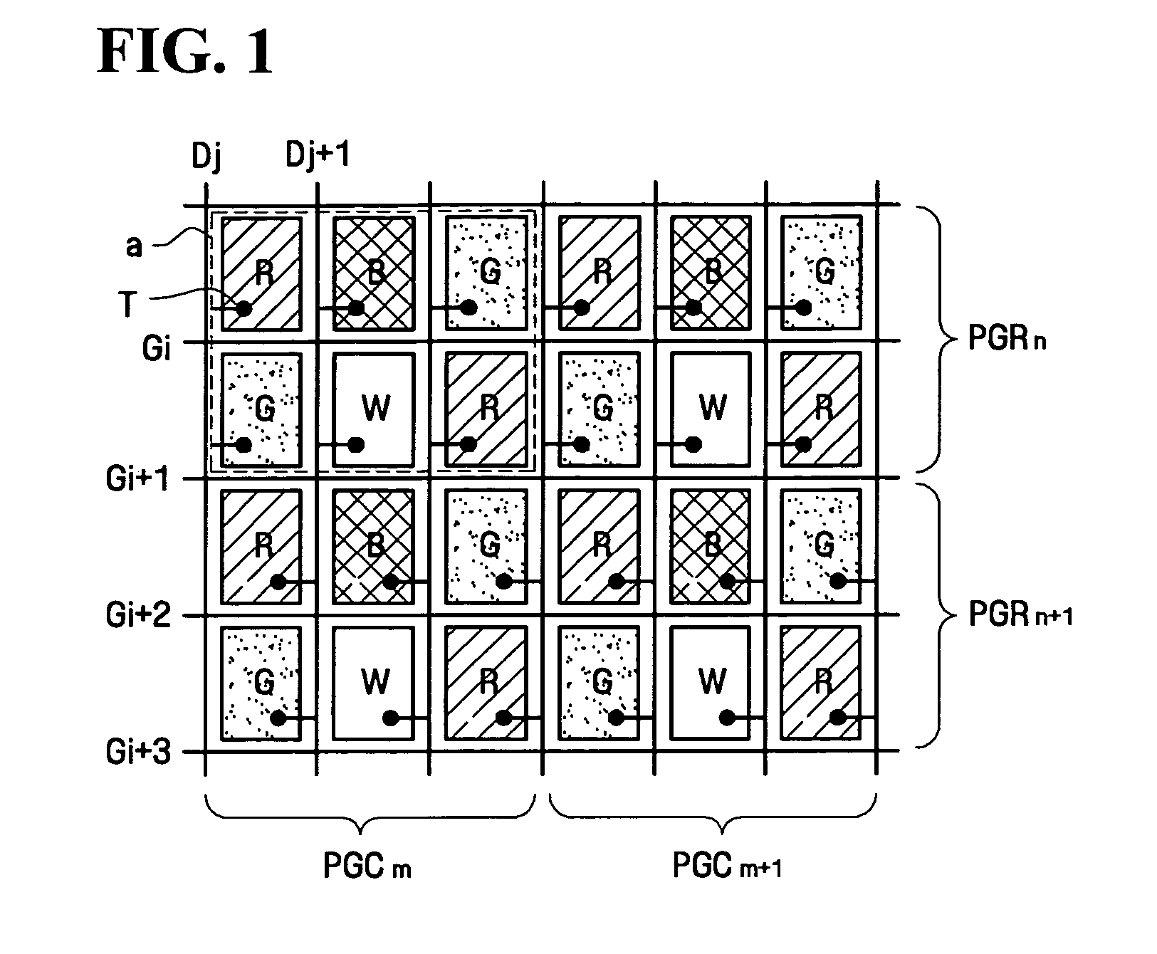
Figure 2 
Figure 3
Abstract
Description
BACKGROUND OF THE INVENTION
[0001] 1. Field of the Invention
[0002] The present invention relates to an image display device, and more particularly, to a liquid crystal display (LCD) device for displaying high-resolution images and a driving method for the same.
[0003] 2. Description of the Related Art
[0004] In general, an LCD device has a liquid crystal material injected into a space between a color filter substrate on which common electrodes and color filters are formed, and a thin-film transistor (TFT) substrate on which TFT and pixel electrodes are formed. In such an LCD device, images are represented by changing an arrangement of liquid crystal particles by applying different potentials to the pixel electrodes and the common electrodes, thereby controlling the light transmittance of the liquid crystal. Controlling the light transmittance of the liquid crystal allows a control of light passing through the LCD.
[0005] There are several types of arrangement of the color filters. ...
Examples
first embodiment
[0032] A liquid crystal display (LCD) device and a method of driving the same according to the present invention will now be described.
[0033]FIG. 1 is a schematic diagram illustrating an arrangement of pixels and switching devices in an LCD device according to the first embodiment of the present invention.
[0034] Referring to FIG. 1, the LCD according to the first embodiment of the present invention includes color filters of red pixels R, blue pixels B, green pixels G, and white pixels W, arranged in a matrix pattern. The red pixel R of the first row is arranged in the same column as the green pixel G of the second row, the blue pixel B of the first row is arranged in the same column as the white pixel W of the second row, and the green pixel G of the first row is arranged in the same column as the red pixel R of the second row. Thus, the red pixels R of the first and second rows face each other diagonally from opposite sides of the blue pixel B and the white pixel W. Similarly, the...
second embodiment
[0059] Next, an LCD and a driving method thereof according to the present invention will be described in greater detail.
[0060]FIG. 6 is a schematic diagram illustrating an arrangement of pixels and switching devices in the LCD device according to the second embodiment of the present invention, and FIG. 7 illustrates the arrangement of pixels and a TFT substrate of the LCD device according to the second embodiment of the present invention.
[0061] As shown in FIGS. 6 and 7, most structure of the LCD device according to the second embodiment of the present invention is the same as that of the LCD device according to the first embodiment of the present invention, except for the arrangement of the pixels and some portions of the structure.
[0062] In the LCD device according to the second embodiment of the present invention, red pixels R, blue pixels B, green pixels G, and white pixels W are arranged in a matrix pattern. The matrix pattern includes, a red pixel R, a blue pixel B, a green ...
third embodiment
[0068] An LCD device and a driving method thereof according to the present invention will now be described.
[0069]FIG. 8 is a schematic diagram illustrating an arrangement of pixels and switching devices in the LCD device according to the third embodiment of the present invention, and FIG. 9 illustrates the arrangement of pixels and a TFT substrate of the LCD device according to the third embodiment of the present invention.
[0070] As shown in FIGS. 8 and 9, the structure of the LCD device according to the third embodiment of the present invention is the same as that of the LCD device according to the first or second embodiment of the present invention, except for the arrangement of the pixels, and the LCD device according to the third embodiment of the present invention can be driven by the same driving method as the LCD device according to the first embodiment of the present invention.
[0071] In the LCD device according to the third embodiment of the present invention, red pixels R...