
Method for repair and replacement of combustor liner panel
a combustor and liner panel technology, applied in manufacturing tools, forging/pressing/hammering apparatus, lighting and heating apparatus, etc., can solve the problems of low cycle fatigue life, inability to repair welds, and cracks in inner liners after engine use, etc., to achieve cost saving, less expensive, and durable
Patent Information
- Authority / Receiving Office
- US · United States
- Patent Type
- Applications(United States)
- Current Assignee / Owner
- Publication Date
- 2006-02-02
Smart Images
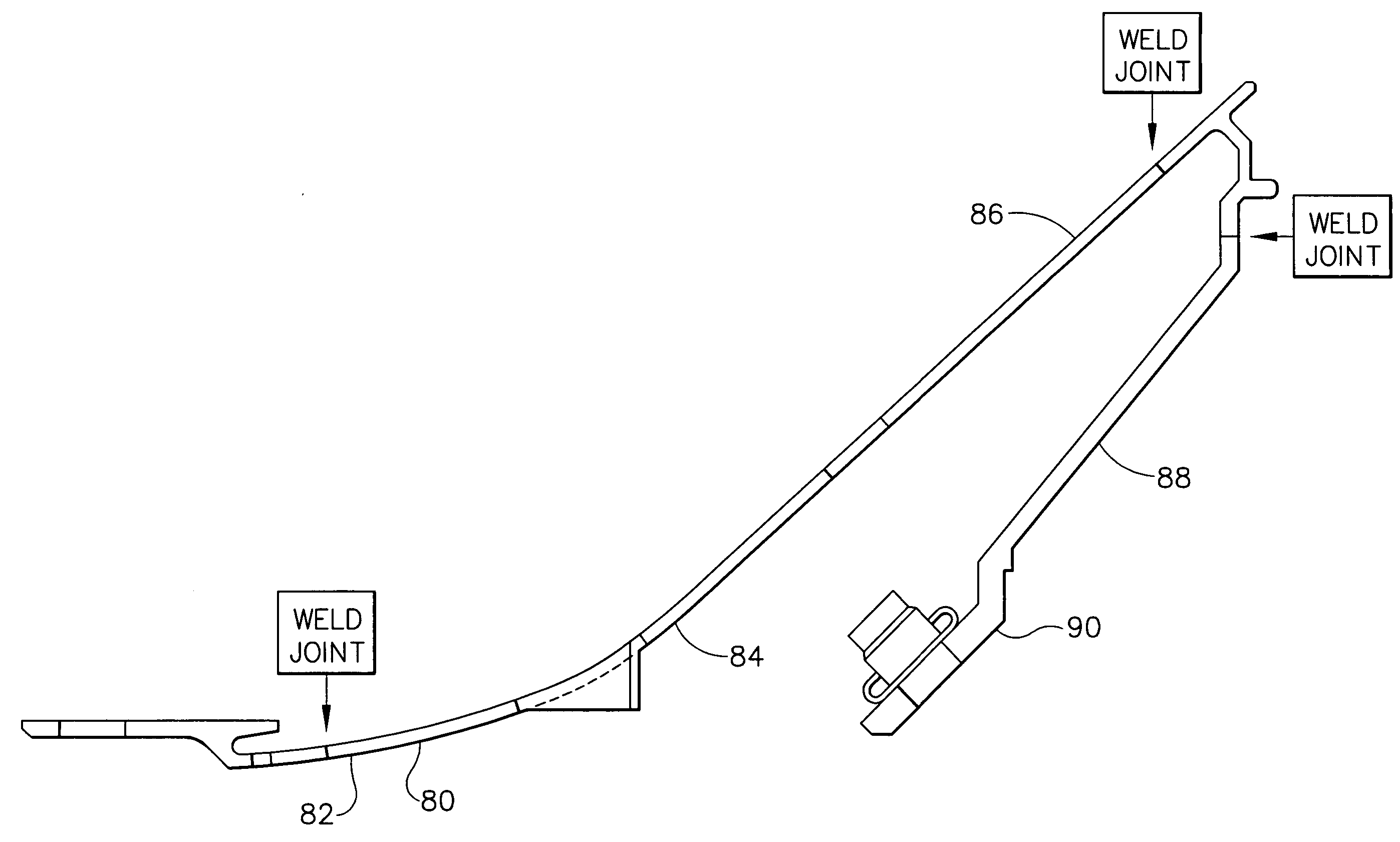
Figure 1 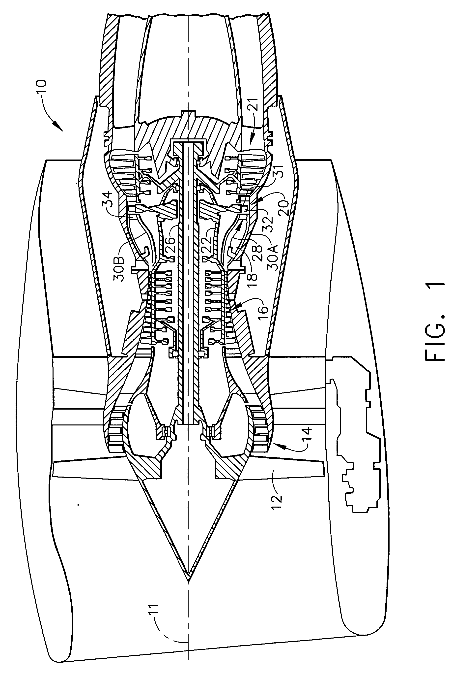
Figure 2 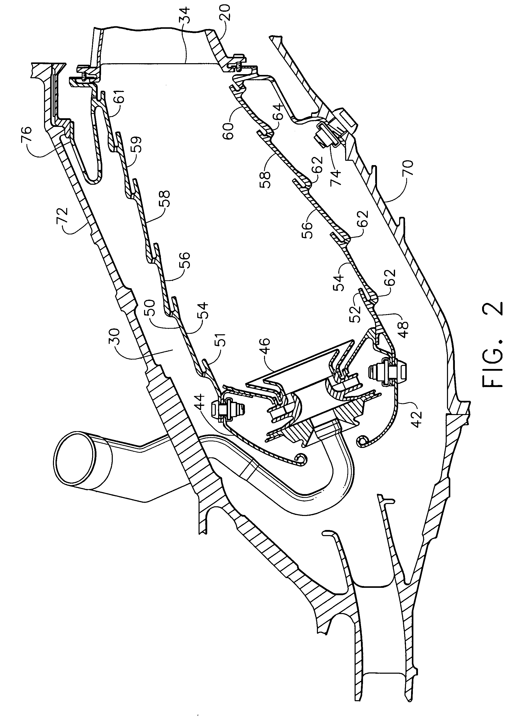
Figure 3
Abstract
Description
FIELD OF THE INVENTION
[0001] The present invention is directed to a method for repair of combustor liner panels, and more specifically to the repair of combustor inner liner panels in large high bypass turbofan engines. BACKGROUND OF THE INVENTION
[0002] A turbine engine used to power aircraft typically includes a compressor section for compressing air, a combustor section for mixing the compressed air with fuel and burning it to generate hot gases, a turbine section in which energy is extracted from the hot gases of combustion to operate the compressor and otherwise provide the aircraft and an exhaust section in which the remaining hot gases of combustion of reduced energy pass to provide thrust which propels the aircraft. A turbofan turbine engine further includes a large fan typically located in front of the compressor. In the case of a front fan, the fan is driven by a second turbine, typically the low pressure turbine, located in the turbine section of the engine behind the hi...
Examples
Embodiment Construction
[0020]FIG. 1 is a schematic of a typical high bypass turbine engine 10. The centerline of the engine is shown at 11, along which the engine shaft 26 is positioned. Air enters the engine 10, passing front fan 12. Some of the air enters the engine core 14 and is directed to the compressor section 16 where it is compressed, while the remainder bypasses the engine core. The compressed air enters the combustion chamber, shown at 30A and 30B where it is mixed with fuel metered from the swirl cup of the fuel injector 18 and ignited. The hot gases of combustion proceed toward the rear of the combustion chamber past the turbine vanes or nozzles 34 and into the turbine rotor 20 where turbine blades 32 in the path of the high pressure gases of combustion are mounted on turbine wheels or disks 31. The high pressure gases pushing on the turbine blades 32 turn the wheels 31 which rotate the engine shaft 26. After the hot gases pass through the turbine section 20, they exit the turbine section at ...