
Fuel cell system and shutdown method for a fuel cell system
Patent Information
- Authority / Receiving Office
- US · United States
- Current Assignee / Owner
- Publication Date
- 2006-03-09
- Estimated Expiration
- Not applicable · inactive patent
Smart Images
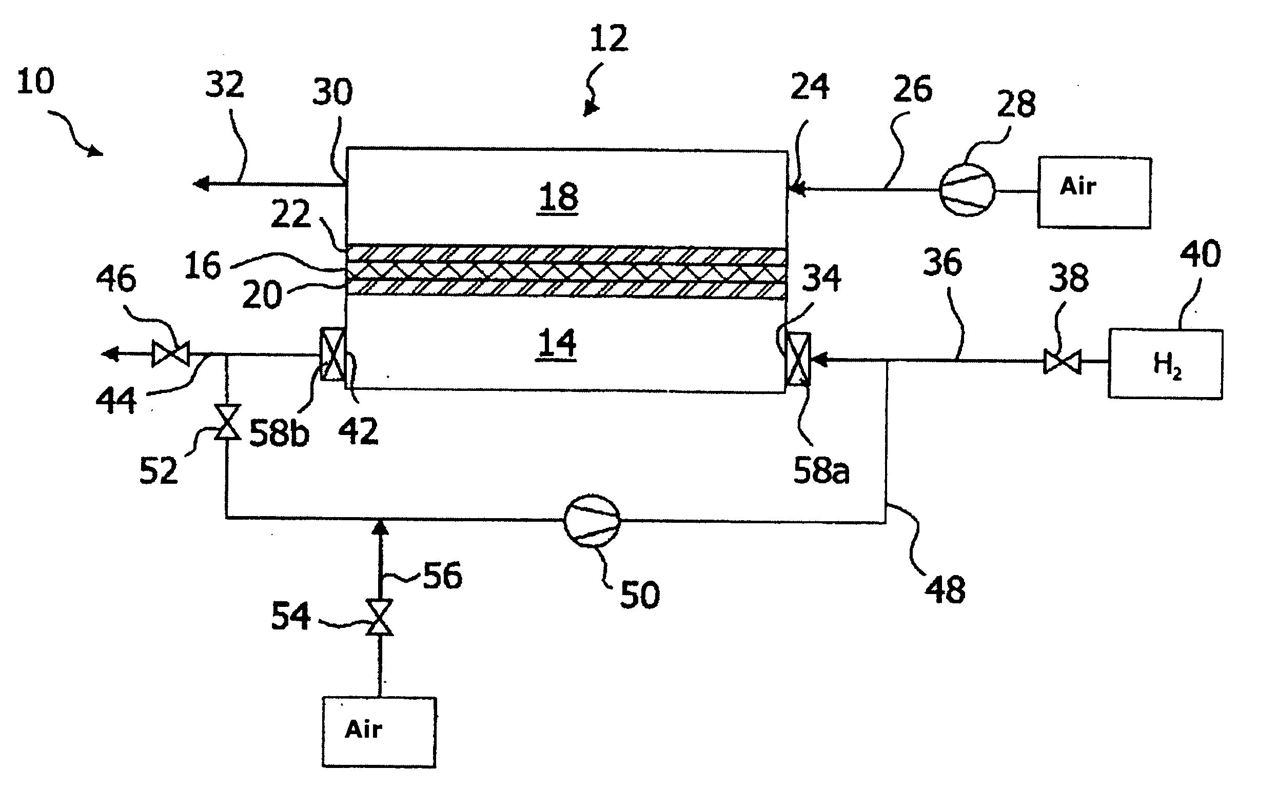
Figure 1 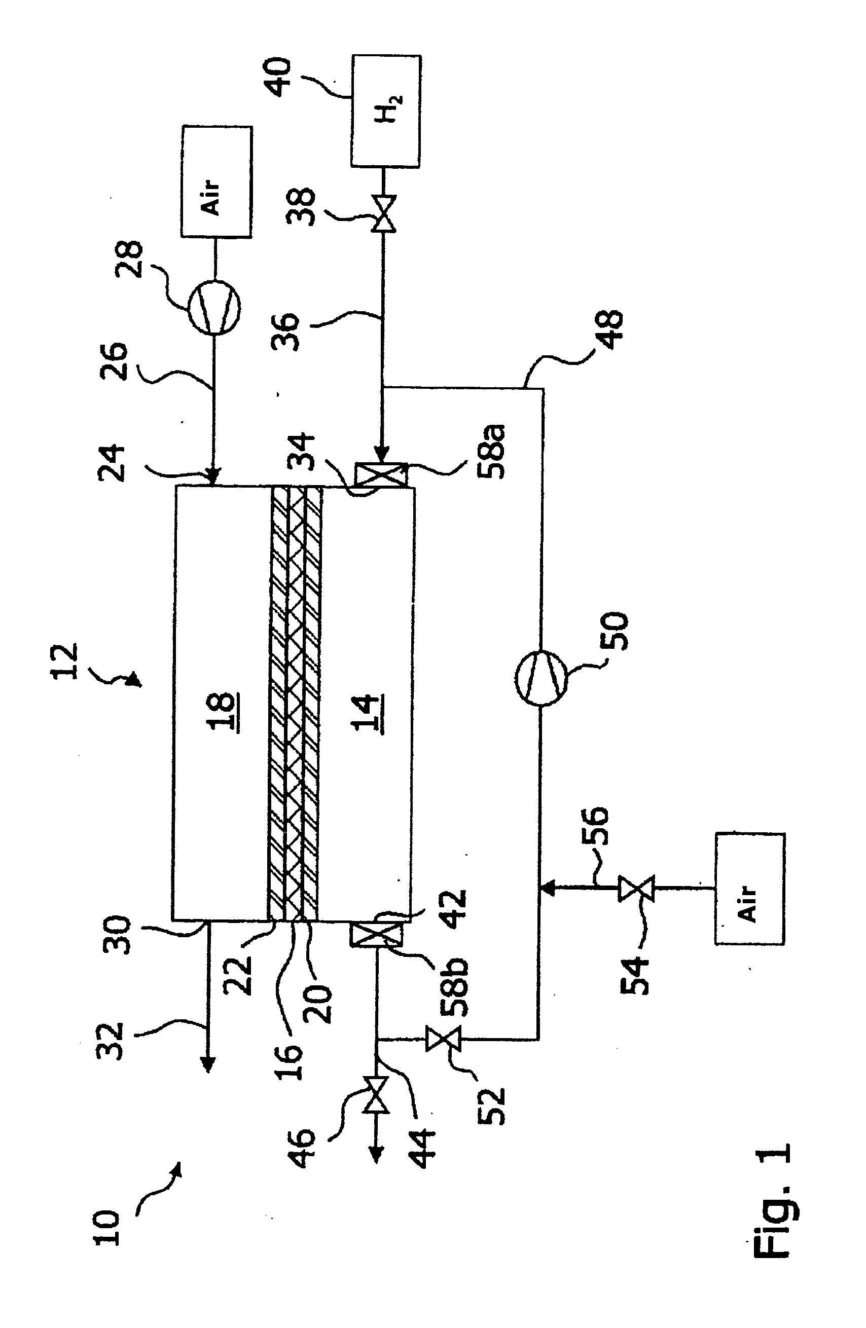
Figure 2 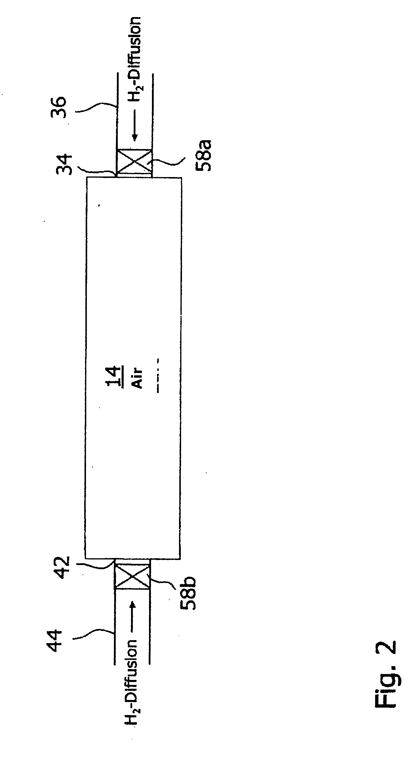
Figure 3
Abstract
Description
CROSS-REFERENCES TO RELATED APPLICATIONS
[0001] This application claims the benefit under 35 U.S.C. § 119(e) of U.S. Provisional Patent Application No. 60 / 654,393 filed Feb. 18, 2005, and also claims priority to German Application No. 10 2004 042 806.9 filed Sep. 3, 2004; both of these applications are incorporated herein by reference in their entireties.BACKGROUND OF THE INVENTION
[0002] 1. Field of the Invention
[0003] The invention generally pertains to a fuel cell system as well as to a method to shut down a fuel cell system.
[0004] 2. Description of the Related Art
[0005] Typical fuel cells in use today comprise one cathode area as well as one anode area, which is separated from the cathode area by an electrolyte. Different electrolytes are used for different types of fuel cells. For example, the electrolyte of a polymer-electrolyte-membrane fuel cell is a proton-conducting membrane. During operation of the fuel cell, the anode side is supplied with hydrogen while the cathode s...
Examples
Embodiment Construction
[0040]FIG. 1 shows a fuel cell system, labelled 10 in its entirety, comprising one fuel cell 12, which contains one anode area 14, as well as one cathode area 18 that is separated from the anode area 14 by an electrolyte 16. The electrolyte 16 is developed in the form of a proton-conducting polymer film. The anode area 14 and the cathode area 18 each contain a catalyst 20, 22, which have been applied onto a carbon carrier (not shown in detail), for the catalytic conversion of reactants supplied to the fuel cell 12. Even though only a single fuel cell 12 is shown in FIG. 1, the fuel cell system 10 comprises a larger number of fuel cells 12, which are stacked on top of each other to form a so-called fuel cell stack.
[0041] The inlet 24 of the cathode area 18 is connected to the ambient air via a cathode gas supply line 26, which contains a pump 28. An outlet 30 of the cathode area 18 opens into a cathode gas discharge line 32.
[0042] An inlet 34 of the anode area 14 is connected to a ...