
Needle Plate for Double-Needle Sewing Machine
Patent Information
- Authority / Receiving Office
- US · United States
- Current Assignee / Owner
- Publication Date
- 2007-05-03
- Estimated Expiration
- Not applicable · inactive patent
Smart Images
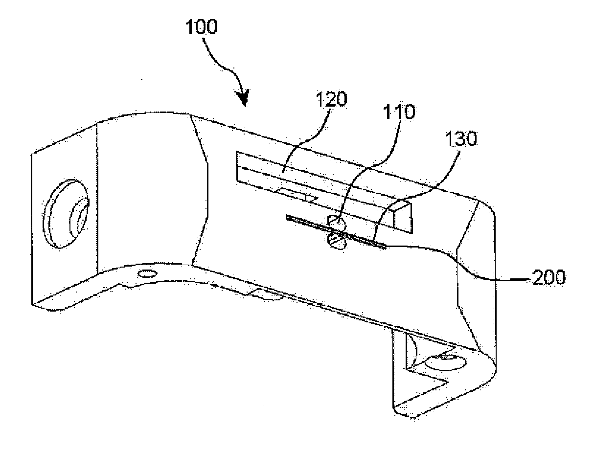
Figure 1 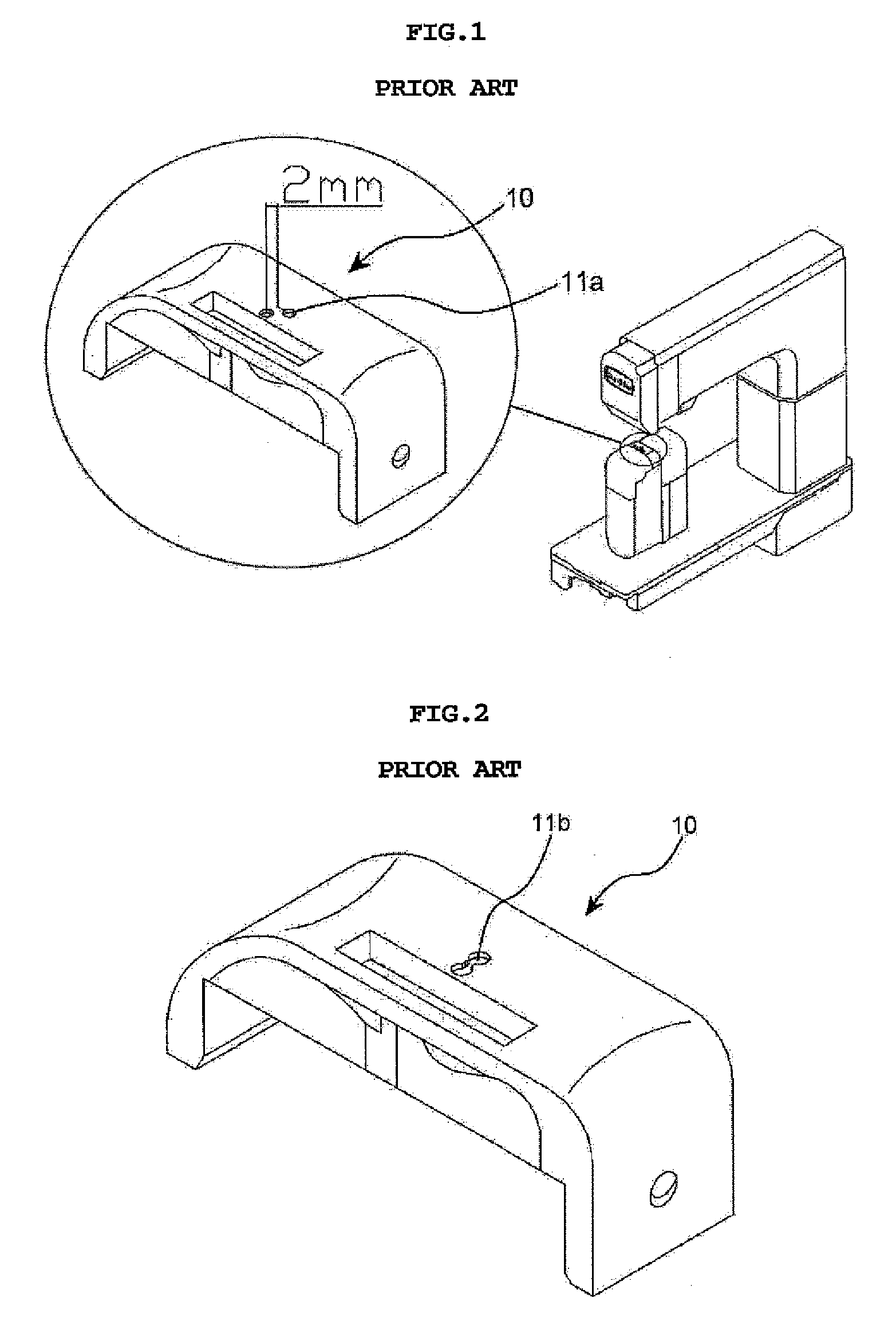
Figure 2 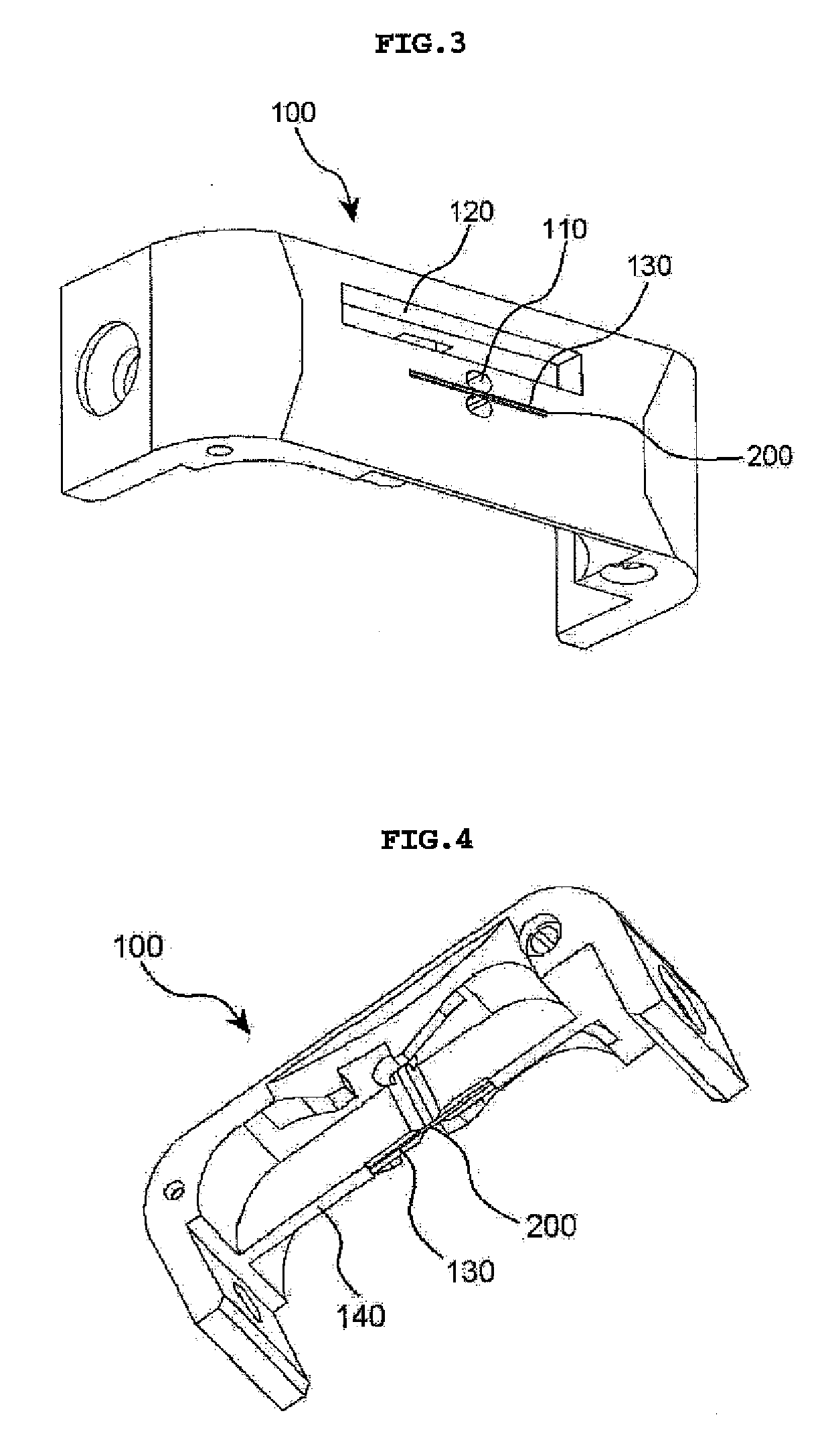
Figure 3
Abstract
Description
BACKGROUND OF THE INVENTION
[0001] 1. Field of the invention
[0002] The present invention relates generally to a double-needle sewing machine, and more particularly, to a needle plate for a double-needle sewing machine that sews the edge of a thick workpiece with two lines of stitches.
[0003] 2. Description of the Prior Art
[0004] FIGS. 1 and 2 are perspective views showing a needle plate for a conventional double-needle sewing machine.
[0005] A needle plate 10 used in a conventional double-needle post bed sewing machine has two needle holes 11a formed on the cross as shown in FIG. 1 or two needle holes 11b oppositely formed in parallel as shown in FIG. 2.
[0006] However, as shown in FIG. 2, on doing proximity sewing work of 2 mm or less using the later needle plate 10 in which the two needle holes 11b are opposite to each other, the interval between the two needle holes 11b is narrow, and thus the needle plate between the two needle holes 11b has been frequently broken due to interf...
Examples
Embodiment Construction
[0019] Hereinafter, exemplary embodiments of the present invention will be described with reference to the accompanying drawings. In the following description and drawings, the same reference numerals are used to designate the same or similar components, and so repetition of the description on the same or similar components will be omitted.
[0020]FIG. 3 is a top perspective view showing a state in which a thin plate is coupled to a needle plate for a double-needle sewing machine according to an embodiment of the present invention, and FIG. 4 is a bottom perspective view of FIG. 3. FIG. 5 is a top perspective view showing a state in which a thin plate is decoupled from a needle plate for a double-needle sewing machine according to an embodiment of the present invention, and FIG. 6 is a bottom perspective view of FIG. 5.
[0021] Referring to FIGS. 3 through 6, the needle plate 100 for a double-needle sewing machine according to an embodiment of the present invention is formed with a tr...