
Bar Code Reading Apparatus and Bar Code Reading Method
Patent Information
- Authority / Receiving Office
- US · United States
- Current Assignee / Owner
- Publication Date
- 2009-11-05
- Estimated Expiration
- Not applicable · inactive patent
Smart Images
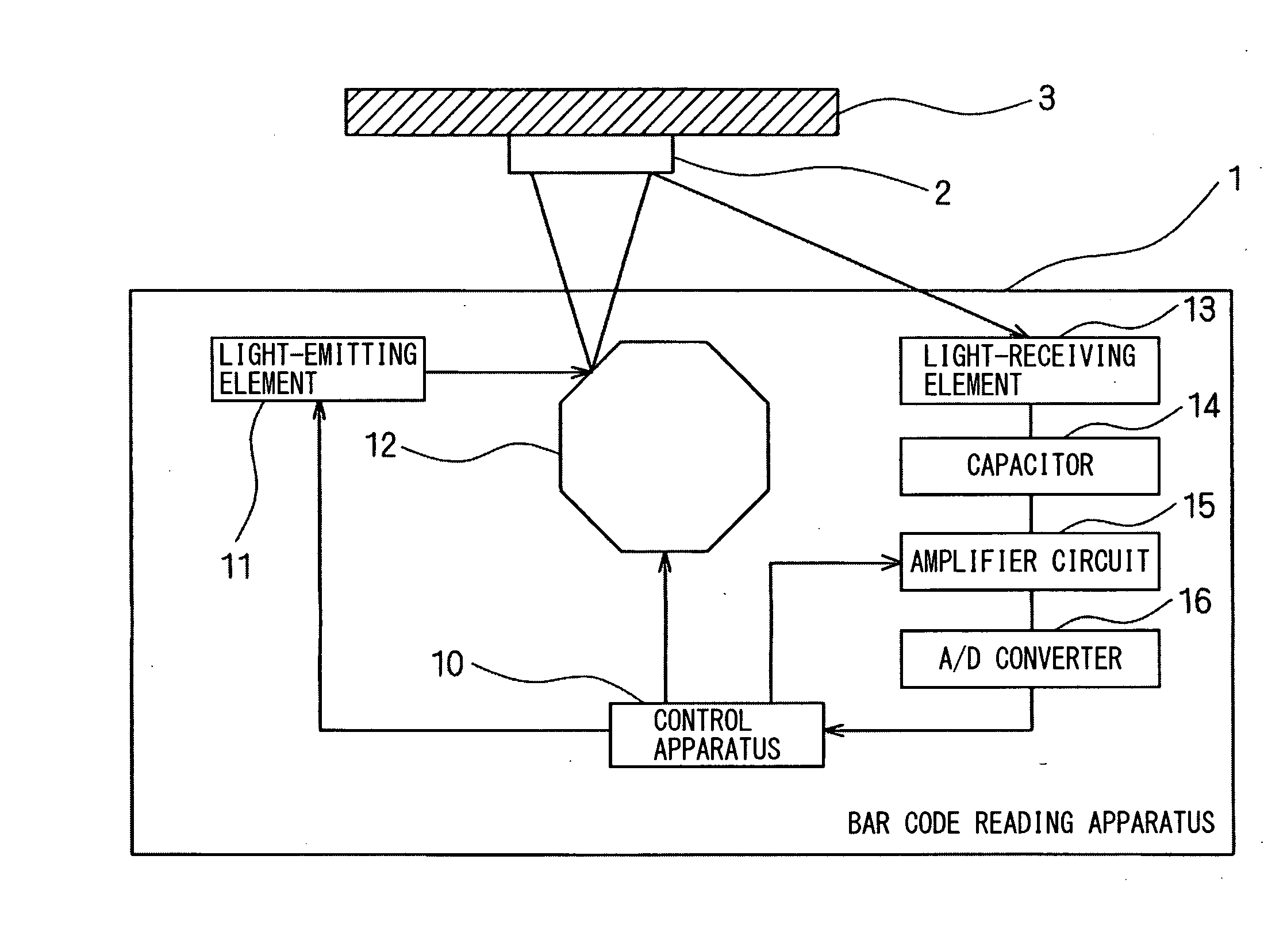
Figure 1 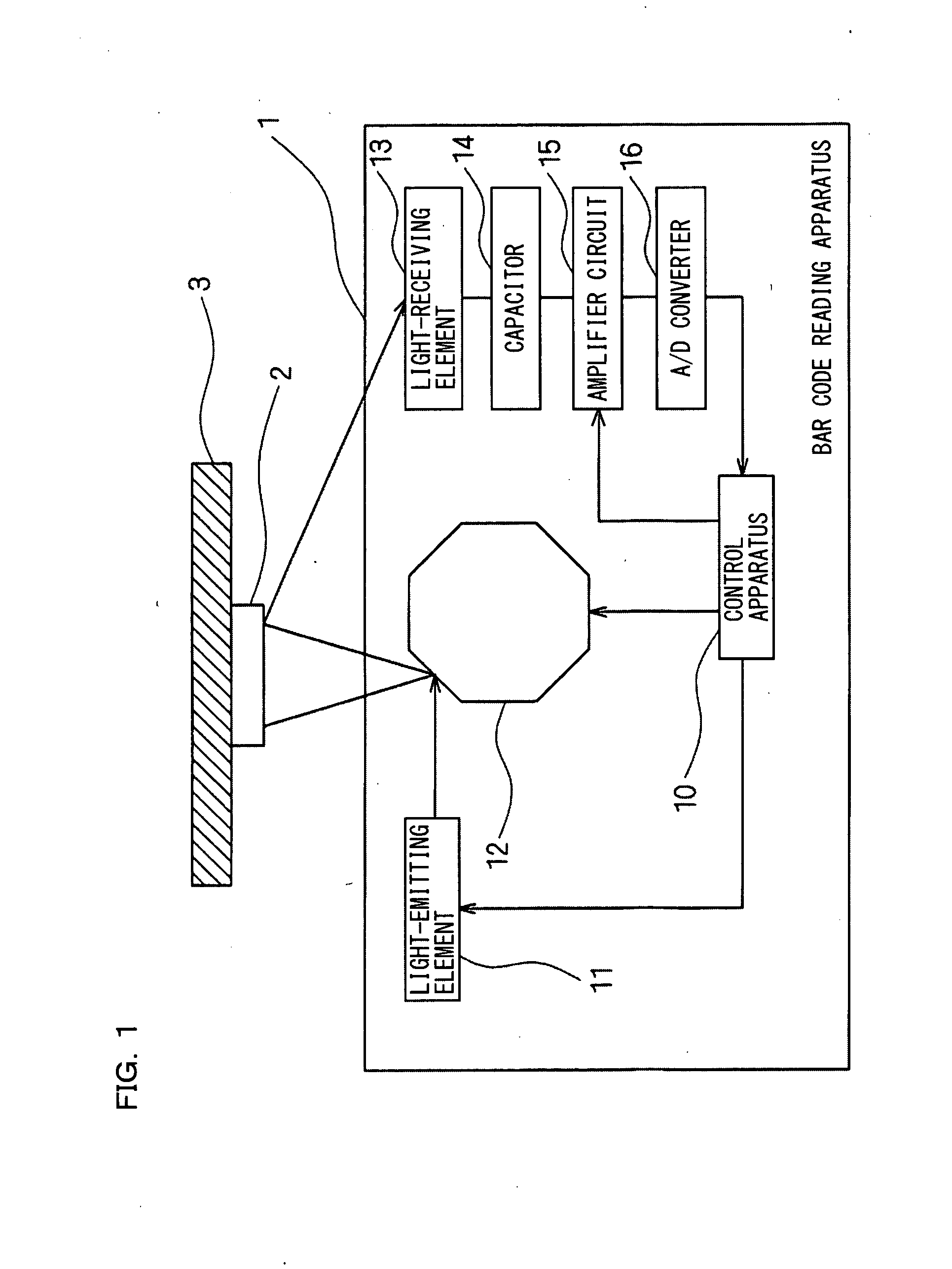
Figure 2 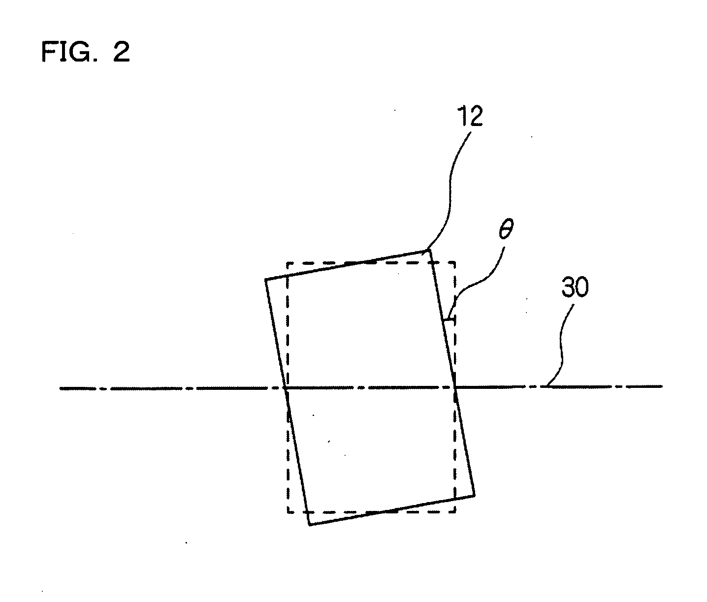
Figure 3
Abstract
Description
CROSS-REFERENCE TO RELATED APPLICATIONS
[0001] The present application claims foreign priority based on Japanese Patent Application No. 2008-118712, filed Apr. 30, 2008, the contents of which is incorporated herein by reference.BACKGROUND OF THE INVENTION
[0002] 1. Field of the Invention
[0003] The present invention relates to a raster scan type bar code reading apparatus and a bar code reading method. More particularly, the present invention relates to a raster scan type bar code reading apparatus and a bar code reading method that are capable of making optimal gain adjustment based on a reading result.
[0004] 2. Description of the Related Art
[0005] Conventionally, numbers of bar code readers have been developed that use semiconductor laser as a light-emitting element and scan a bar code by a light beam. To ensure scanning of a bar code, a light-receiving element needs to receive reflected light of a light beam emitted from a light-emitting element, at an appropriate intensity of received l...
Examples
first embodiment
[0037]FIG. 1 is a block diagram schematically showing a configuration of a bar code reading apparatus according to a first embodiment of the present invention. As shown in FIG. 1, in a bar code reading apparatus 1 according to the first embodiment, light is emitted from a light-emitting element 11, such as semiconductor laser or an LED, and the light is reflected off a surface of a polygon mirror 12 which is a mirror mechanism, toward a to-be-detected object 3.
[0038]The reflected light that is reflected off the polygon mirror 12 is guided to a bar code 2 affixed to the to-be-detected object 3. A light-receiving element 13, such as a CCD or a photodiode, receives reflected light from the bar code 2 and outputs a received-light signal obtained by photoelectrically converting the received reflected light. A direct-current component of the received-light signal is eliminated by a capacitor 14, the resulting received-light signal is amplified according to a gain value set by an amplifier...
second embodiment
[0094]A configuration of a bar code reading apparatus according to a second embodiment of the present invention is the same as that of the first embodiment and thus the same reference numerals are provided and a detailed description thereof is not given. Although the second embodiment is the same as conventional cases in performing a reading process at each scanning line, the second embodiment is different from the first embodiment in that a determination as to whether reading has been able to be performed normally is made for each scanning line and if reading has not been able to be performed normally, then a plurality of gain values stored in advance are repeatedly set in a predetermined order.
[0095]FIG. 11 is a flowchart showing steps of a gain value modification process performed by a CPU 20 of a control apparatus 10 of a bar code reading apparatus 1 according to the second embodiment of the present invention. In FIG. 11, the CPU 20 of the control apparatus 10 sets a counter n t...