
Backlight module
Patent Information
- Authority / Receiving Office
- US · United States
- Current Assignee / Owner
- Publication Date
- 2010-04-01
Smart Images
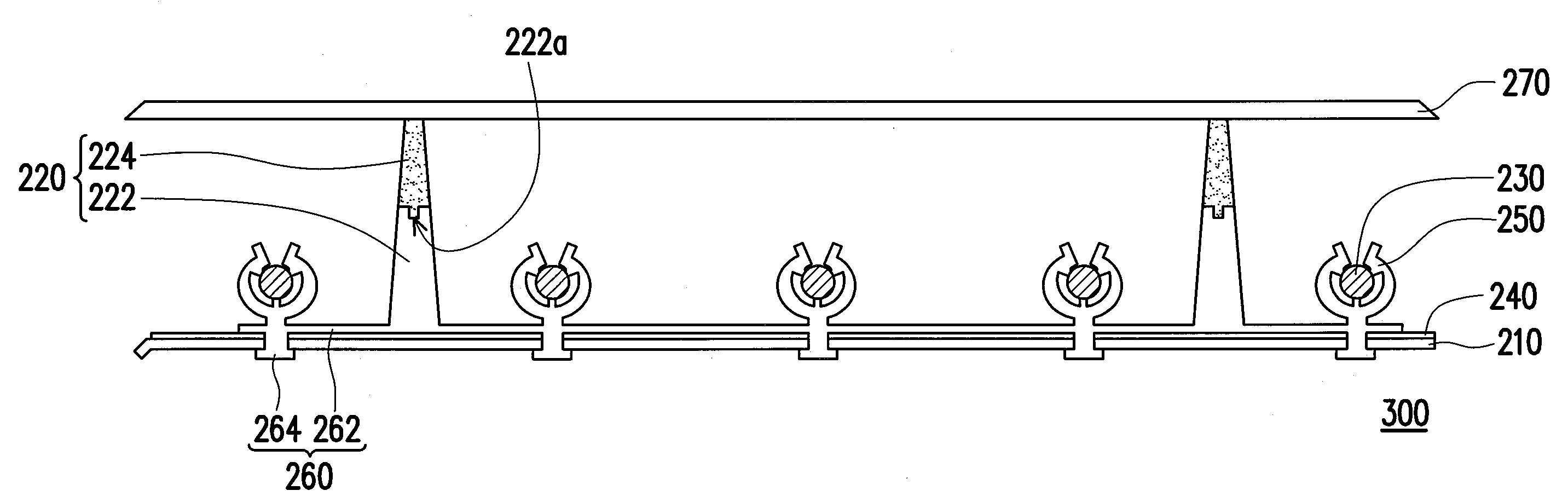
Figure 1 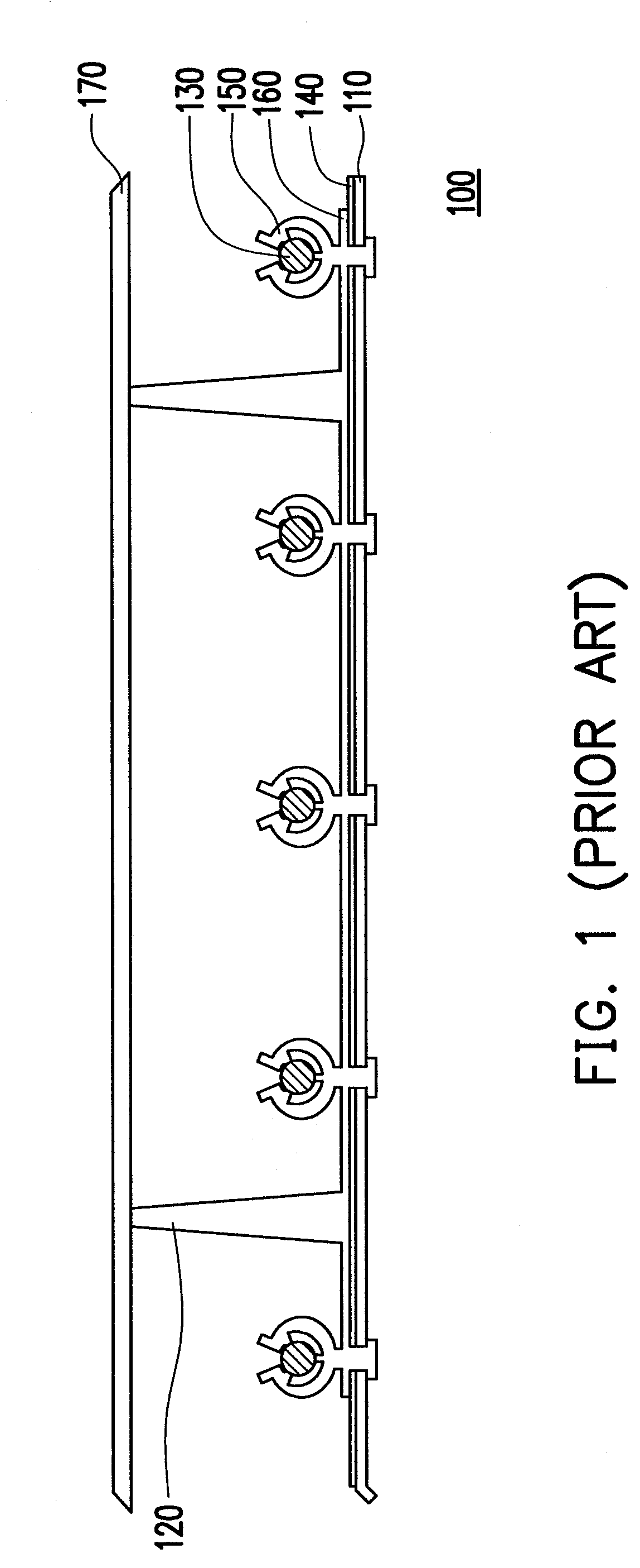
Figure 2 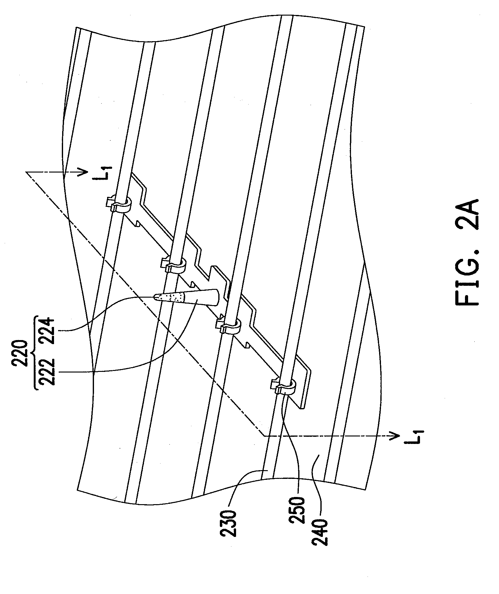
Figure 3
Abstract
Description
CROSS-REFERENCE TO RELATED APPLICATION
[0001] This application claims the priority benefit of Taiwan application serial no. 97137211, filed Sep. 26, 2008. The entirety of the above-mentioned patent application is hereby incorporated by reference herein and made a part of this specification.BACKGROUND OF THE INVENTION
[0002] 1. Field of the Invention
[0003] The present invention generally relates to a backlight source, and more particularly, to a backlight module having a buffering supporter.
[0004] 2. Description of Related Art
[0005] With fast development of the displaying technology, people, facilitated with those developed display devices, are living with more convenience. Flat panel displays (FPD), having the advantages of light-weight and thin-volume, have become the main stream of the display market. Comparing with most other kinds of FPDs, liquid crystal displays (LCD) have presented superior characteristics, such as better space utilization, lower power consumption, non-radiation, and...
Examples
first embodiment
[0028]FIG. 2A is a partial schematic view of a backlight module according to a first embodiment of the present invention. FIG. 2B is a partial cross-sectional view ofFIG. 2A along cutting line L1-L1. Referring to FIGS. 2A and 2B together, a backlight module 200 is shown. The backlight module 200 includes a backplate 210, at least one supporter 220, and a plurality of light emitting devices 230. The supporter 220 is disposed on the backplate 210. The light emitting devices 230 are disposed on the backplate 210. The supporter 220 is disposed between the light emitting devices 230. The light emitting devices 230 are adapted for providing a light source. The backlight module 200 may further include a reflection sheet. When the reflection sheet 230 is disposed on the backplate 210, facing toward the light emitting devices 230, linear light sources provided by the light emitting devices 230 can be reflected by the reflection sheet 240 to obtain a uniform plane light source.
[0029]In the pr...
second embodiment
[0036]FIG. 3 is a partial cross-sectional view of a backlight module according to a second embodiment of the present invention. Referring to FIG. 3, it shows a backlight module 300 similar to the backlight module 200 of the first embodiment. The difference between the two embodiments is the configuration of the conjunction of the supporting portion 222 and the buffering portion 224.
[0037]As shown in FIG. 3, the supporting portion 222 has a recess 222a at one side of the supporting portion 222 adjacent to the buffering portion 224 and a part of the buffering portion 224 is located in the recess 222a. In practice, the recess 222a for example is configured at the side of the supporting portion 222 apart from the substrate 260. Specifically, during the injection molding process, the supporting portion 222 having a recess 222a is fixed in a mold. Then a material for making the buffering portion 224, e.g., TPU, is injected into the mold to form the buffering portion 224 on the supporting ...
third embodiment
[0040]FIG. 4 is a partial cross-sectional view of a backlight module according to a third embodiment of the present invention. Referring to FIG. 4, it shows a backlight module 400 similar to the backlight module 200 of the first embodiment and the backlight module 300 of the second embodiment. The difference between the two embodiments is the configuration of the conjunction of the supporting portion 222 and the buffering portion 224.
[0041]As shown in FIG. 4, the buffering portion 224 has a recess 224a at one side of the buffering portion 224 adjacent to the supporting portion 222 and a part of the supporting portion 222 is located in the recess 224a. In other words, in the present embodiment, the supporting portion 222 and the buffering portion 224 are also interfered to each other. And the interference between the supporting portion 222 and the buffering portion 224 can also strengthen the combination between the supporting portion 222 and the buffering portion 224 and avoid the d...