
Method And Circuitry for Improving the Magnitude and Shape of the Output Current of Switching Power Converters
a technology of output current and magnitude, applied in the direction of electric variable regulation, process and machine control, instruments, etc., can solve the problems of system malfunction, severe damage to feeding sources, and limited mode of operation, so as to reduce power and stress of said switches
Patent Information
- Authority / Receiving Office
- US · United States
- Patent Type
- Applications(United States)
- Current Assignee / Owner
- Publication Date
- 2010-04-22
- Estimated Expiration
- Not applicable · inactive patent
Smart Images
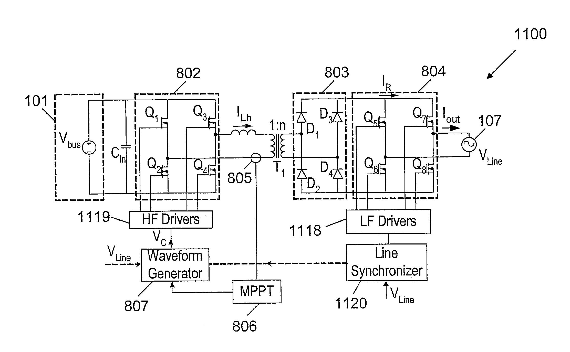
Figure 1 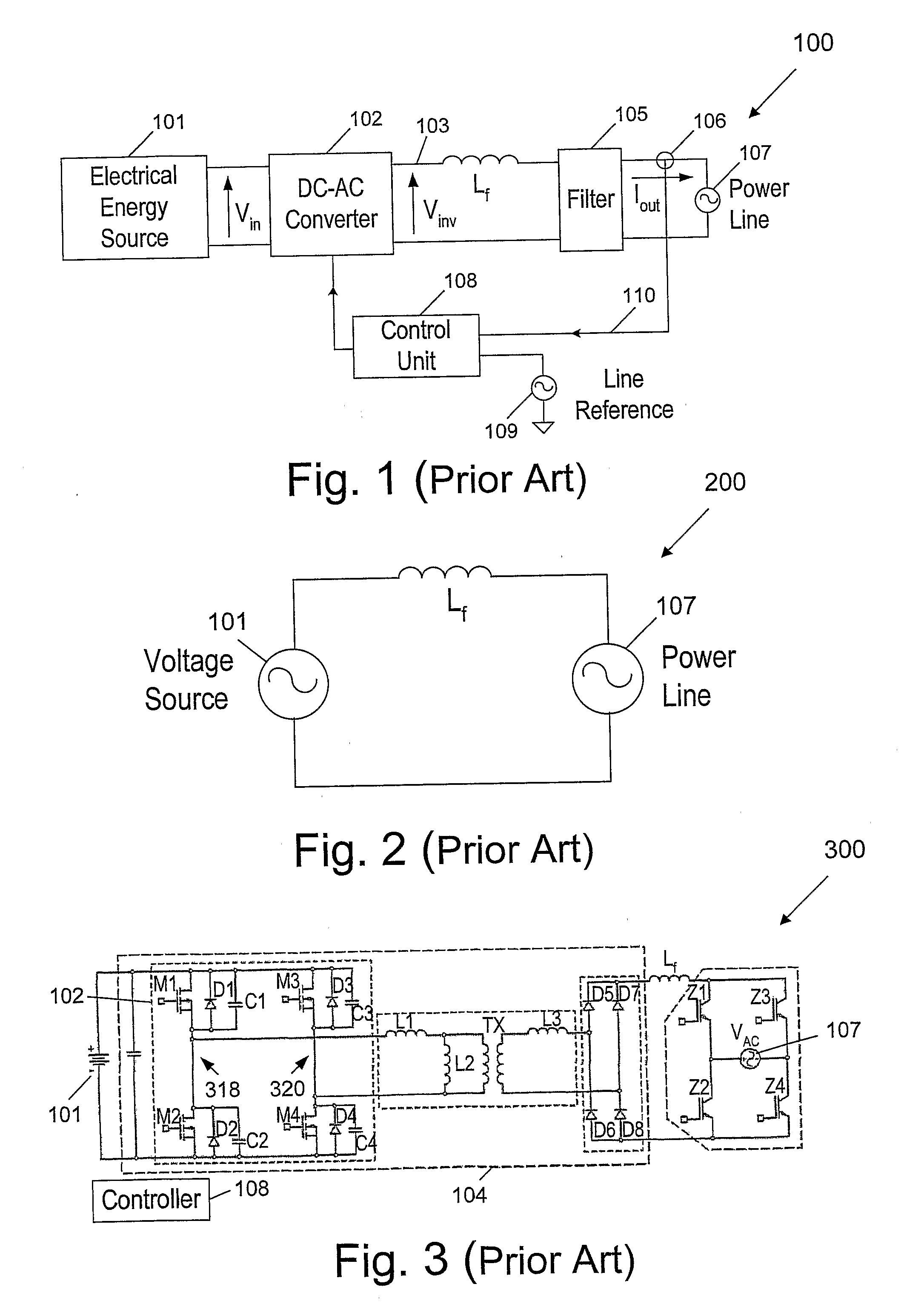
Figure 2 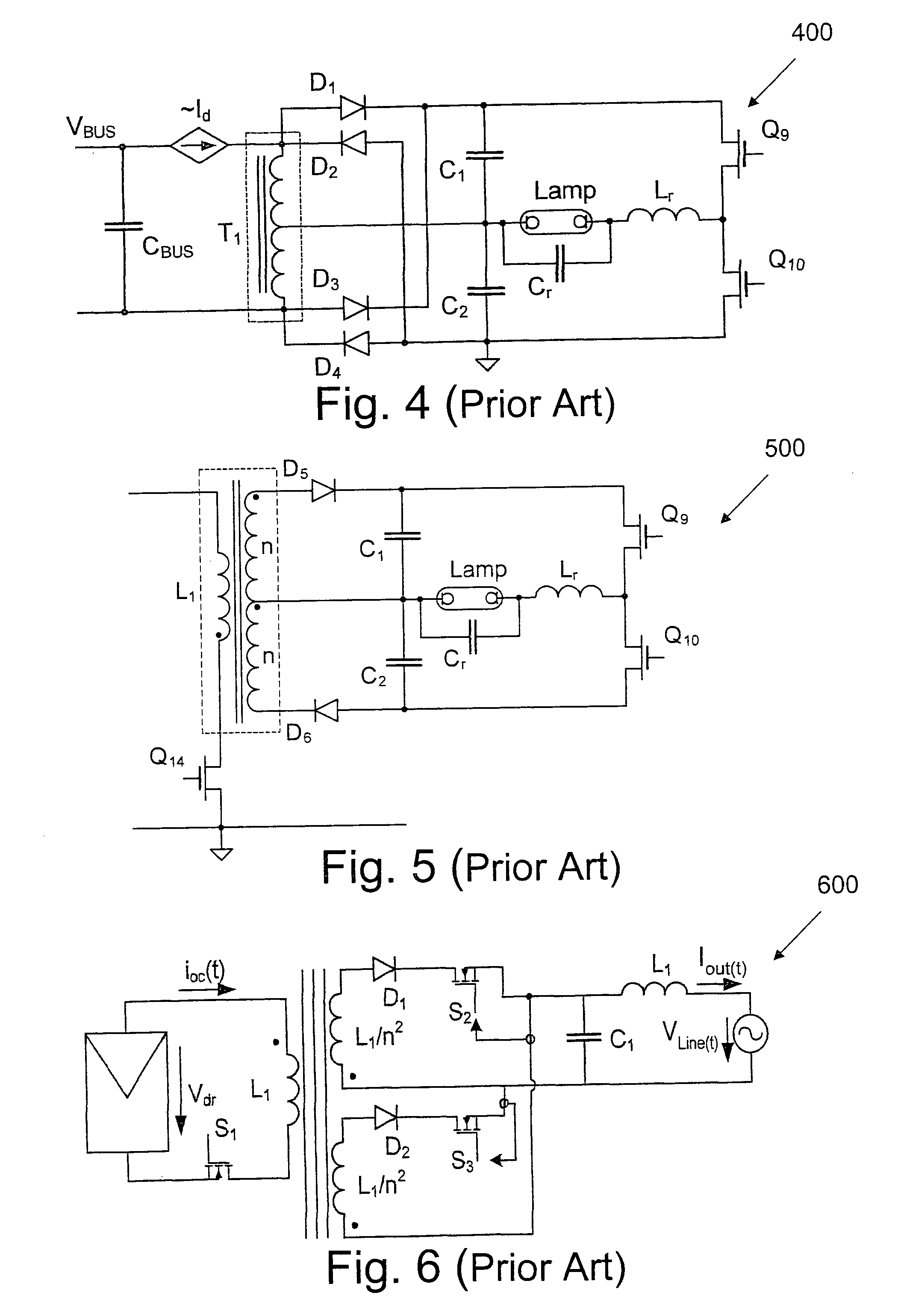
Figure 3
Abstract
Description
FIELD OF THE INVENTION
[0001] The present invention relates to switching power converters. More particularly, the invention relates to a method and circuitry for improving the magnitude and shape of the output current of switching power converters.BACKGROUND OF THE INVENTION
[0002] Currently, there are several types of power converters which are widely used for the DC-to-DC (Direct Current), DC-to-AC (Alternating current), AC-to-DC and AC-to-AC power conversion. In some applications, the purpose of the converter is to provide a regulated output voltage. In other applications, the purpose of the power conversion scheme is to regulate the output current independent of the load voltage. For example, in the case of a battery charger, the converter needs to feed the battery with a current rather than with a fixed output voltage. Another example is a grid-connected inverter for feeding energy into the power line. In this case, the required shape of the current is a sinusoidal waveform synchro...
Examples
Embodiment Construction
[0068]The present invention is directed to a method and circuitry (apparatus) that behaves as an inherent current source, for injecting a sinusoidal current into a power line.
[0069]FIG. 8 is a schematic block diagram 800 of a of a circuitry (apparatus) of a grid-connected inverter for injecting a current into a Power Line 107, according to an embodiment of the present invention. The circuitry of the grid (Power Line 107) connected inverter comprises: an Electrical Energy Source 101 for providing the substantially DC voltage to said circuitry; an Inverter 802 for converting said substantially DC voltage of said Electrical Energy Source 801 to a high frequency alternating voltage Vinv; a Waveform Generator 807 for controlling said high frequency alternating voltage Vinv by means of a control signal Vc fed into said Inverter 802; an inductor Lh connected in series to an output of said Inverter 802 for generating an alternating current ILh due to the high frequency alternating voltage V...