
Material Separator
Patent Information
- Authority / Receiving Office
- US · United States
- Current Assignee / Owner
- Publication Date
- 2011-10-27
- Estimated Expiration
- Not applicable · inactive patent
Smart Images
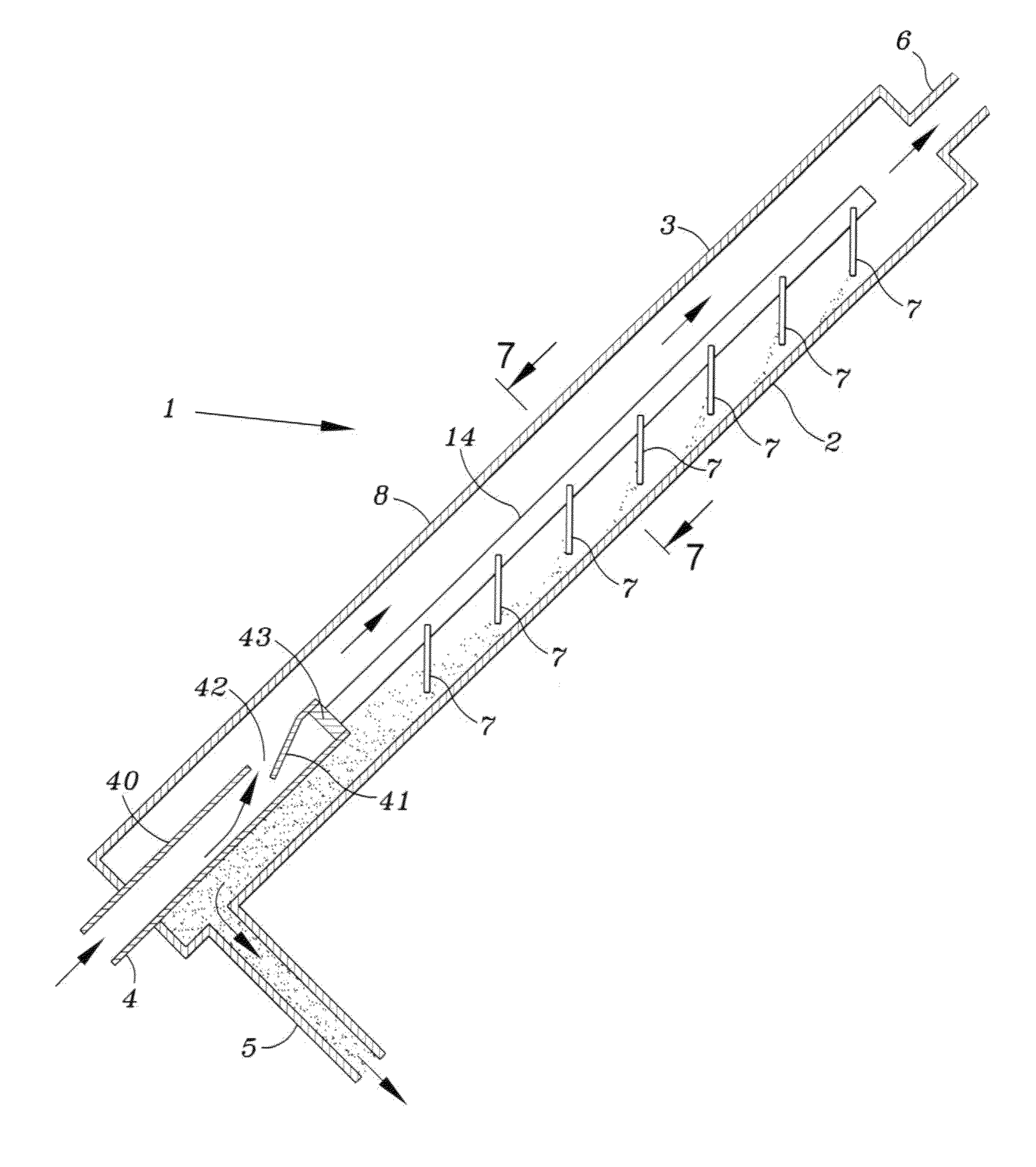
Figure 1 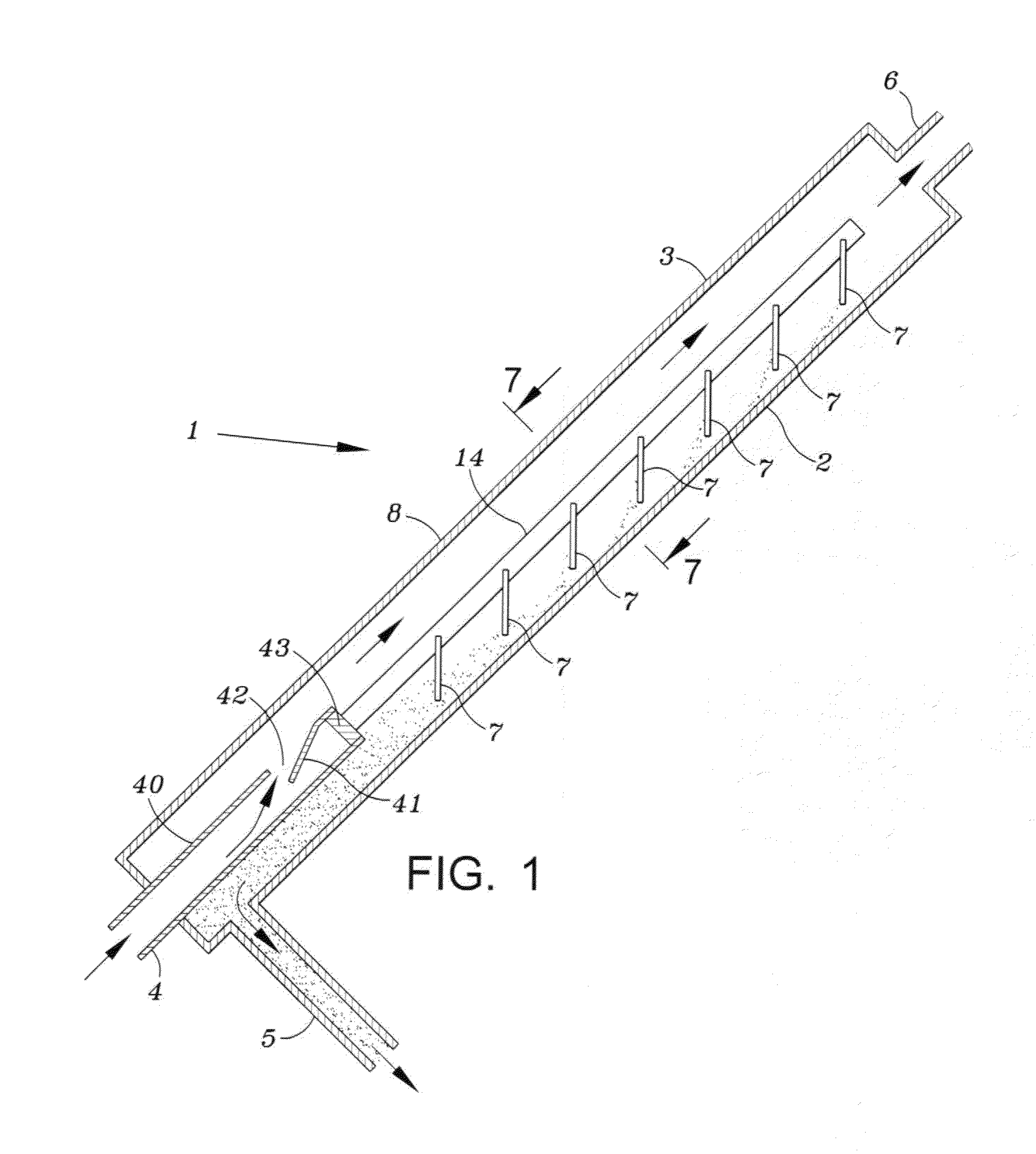
Figure 2 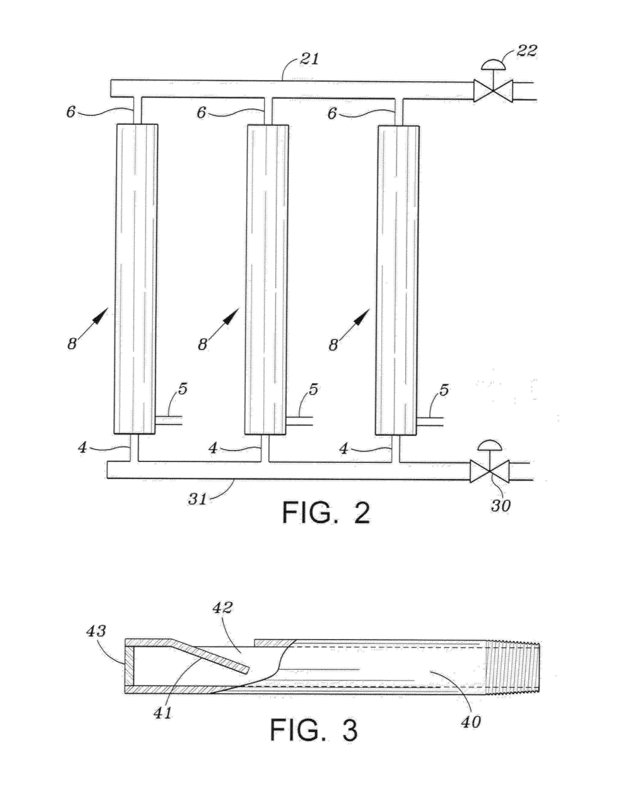
Figure 3
Abstract
Description
BACKGROUND OF THE INVENTION
[0001] 1. Field of Invention
[0002] This invention is directed to a device for separating materials of different density, from a flowing stream of fluid which may contain solids, liquids and gases. The device may be readily transported to remote locations such as oil or gas wells to remove solids, for example sand, from fluid that is used at the well site for various purposes and requires treatment after use.
[0003] 2. Description of Related Art
[0004] Currently sand separation equipment is used following fracturing or well stimulation operations. The sand separators are placed in line in front of the choke manifold and other production piping or equipment. This is done in an effort to avoid erosive damage that can be caused by the sand flowing at high velocities through the equipment. In addition some of the equipment can become damaged or plugged up when the sand settles out inside of the equipment piping or pipe lines. This sand can also damage the equipment b...
Examples
Embodiment Construction
[0018]FIG. 1 illustrates an embodiment of the invention and shows a view of a separator 1. A plurality of separators may be connected to common manifolds for the input fluid, particle removal, and for the output fluid. The separator includes a first elongated body portion 8 having an upper side wall 3 and a lower side wall 2. In use the separator is inclined with respect to the horizontal at an angle of about, but not limited to, twenty to seventy degrees.
[0019]The separator body 8 may be a cylindrical tube having an inlet 4 at the lower portion, an outlet 5 in the lower portion for removal of the separated material, for example sand, and an outlet 6 in an upper portion for the liquid and any gas that may be present in the fluid introduced at the bottom of the body.
[0020]A cylindrical pipe 40 is connected to the inlet 4 and is secured within the body 8. As shown in FIGS. 3 and 5, the wall of the pipe has an outlet 42 formed by cutting a U-shaped slot in the wall and then bending the...