
Low Noise Amplifier with Current Bleeding Branch
Patent Information
- Authority / Receiving Office
- US · United States
- Current Assignee / Owner
- Publication Date
- 2012-02-02
Smart Images
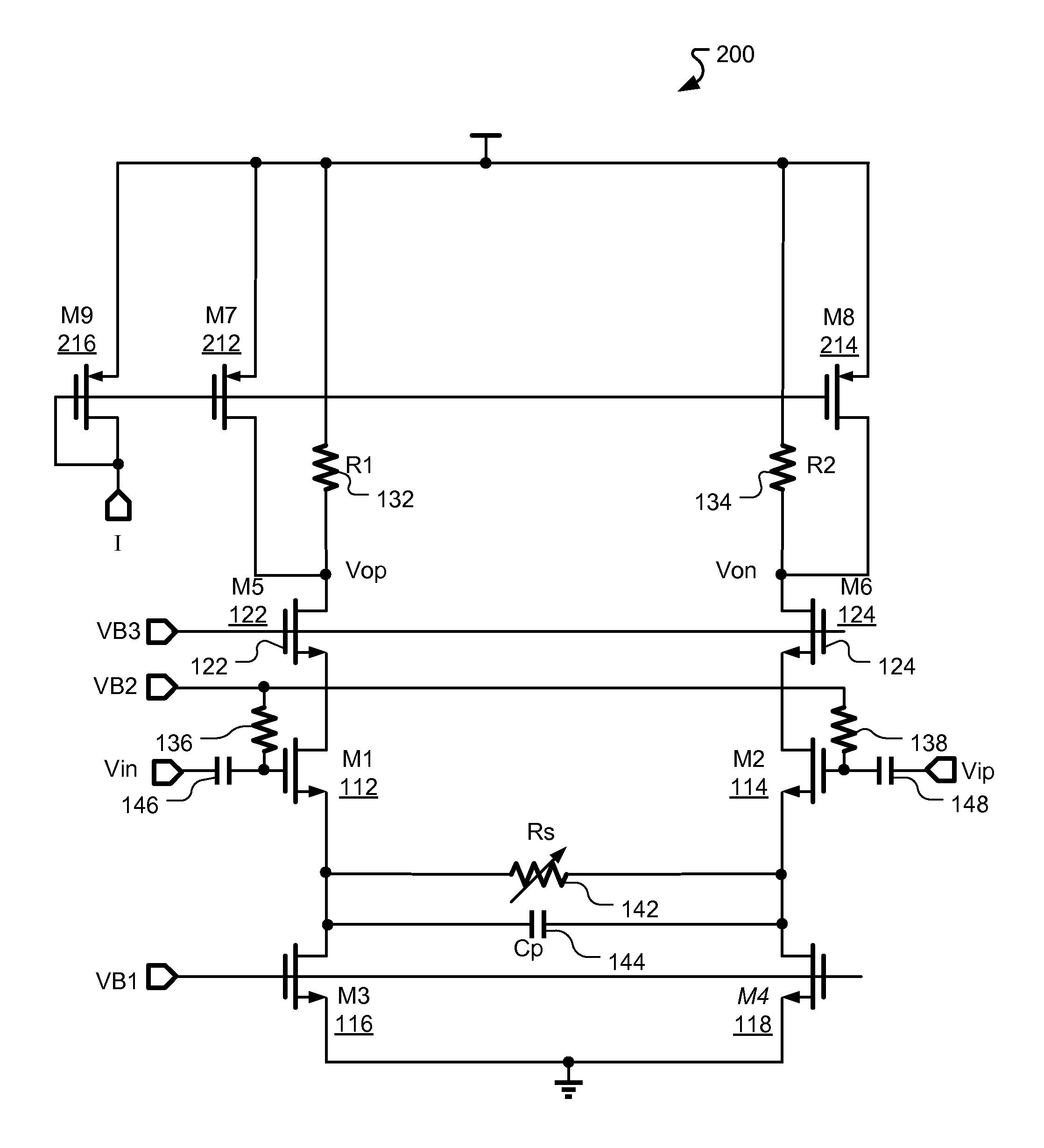
Figure 1 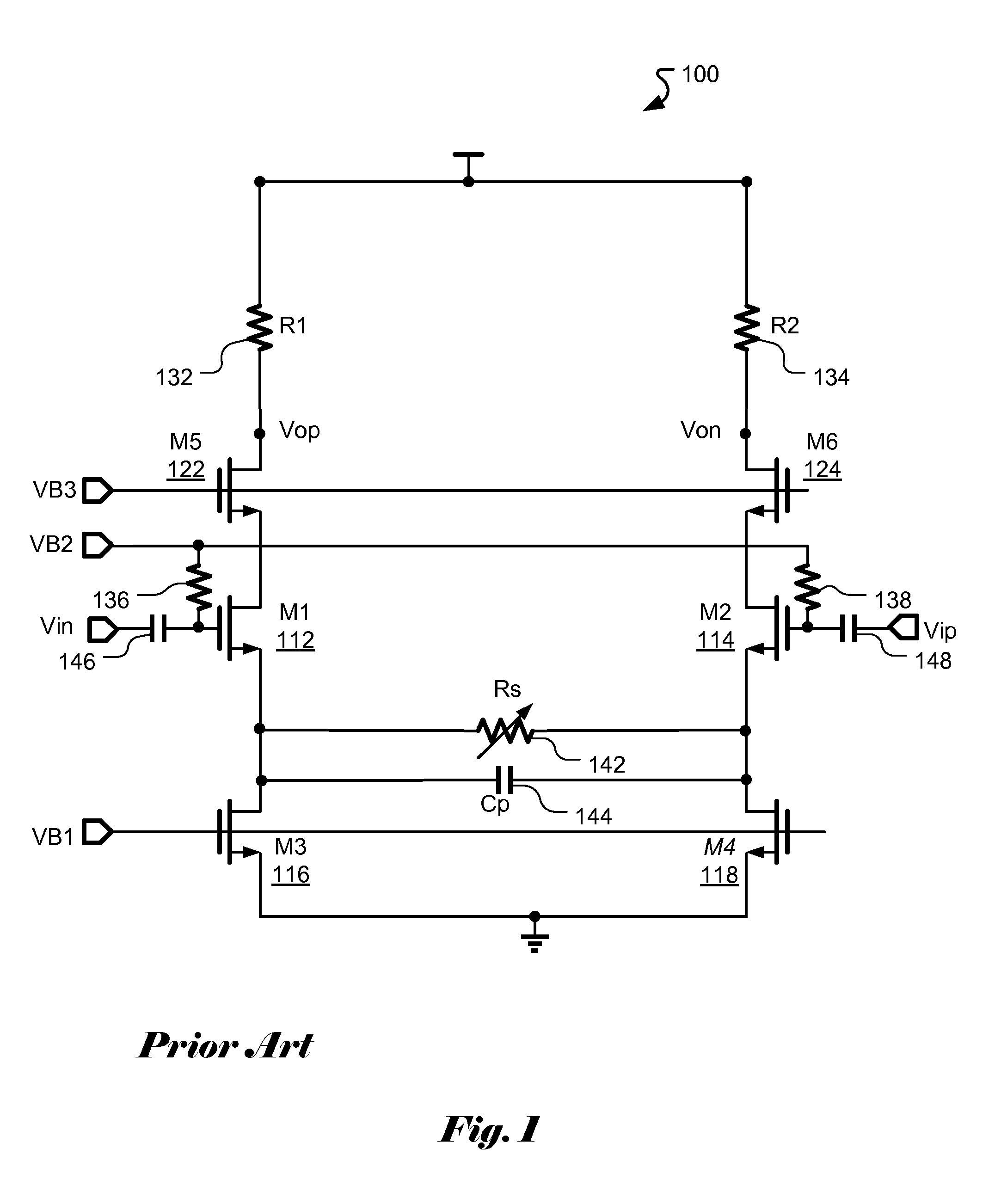
Figure 2 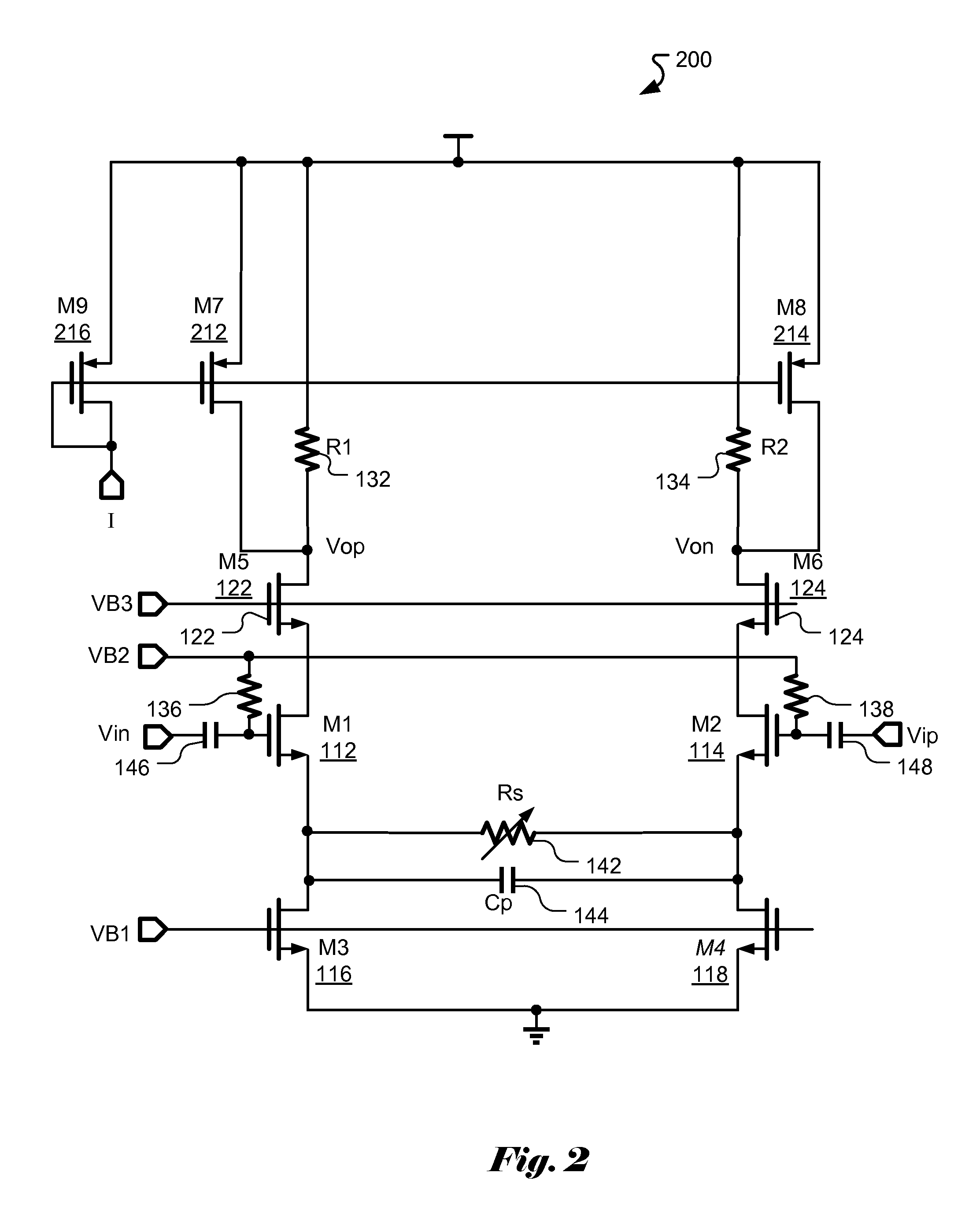
Figure 3
Abstract
Description
CROSS REFERENCE TO RELATED APPLICATIONS
[0001] The present invention claims priority to U.S. Provisional Patent Application No. 61 / 369,708, filed Aug. 1, 2010, entitled “Low Noise Amplifier with Current Bleeding Branch.” The U.S. Provisional Patent Application is hereby incorporated by reference in its entirety.FIELD OF THE INVENTION
[0002] The present invention relates to radio receivers. In particular, the present invention relates to the low-noise amplifier with a current bleeding branch for the radio receiver to operate with a wide range of input signal levels.BACKGROUND
[0003] In a radio frequency (RF) receiver, the signal received by an antenna usually is extremely small. For example, the RF signal received by an antenna for a TV signal may be as low as several micro-volts. The small received signal often is amplified by a low-noise amplifier (LNA) typically with low noise figure (NF) in order to ensure system performance in terms of signal to noise ratio (SNR). The LNA is one of th...
Examples
Embodiment Construction
[0013]FIG. 1 illustrates a conventional implementation of differential low-power amplifier 100 without a current bleeding circuit. The circuit has been widely used as a low-noise amplifier (LNA) for broad band RF receivers. The RF inputs Vin and Vip are AC coupled to the amplifier inputs through two respective AC coupling capacitors 146 and 148. The amplifier can also be configured as a single-ended input amplifier when one of the two inputs is AC grounded. M1112 and M2114 are input transistors and Rs 142 is the source degeneration resistor for adjusting the gain of the LNA. Cp 144 is the parasitic capacitor associated with the input transistors M1112 and M2114 which may limit the effect of source degeneration of resistor Rs 142 at high frequencies. M3116 and M4118 are transistors used as current sources while the transistor pair M5122 and M6124 forms a cascode stage which decouples the inputs and the outputs. VB1, VB2, and VB3 are DC bias voltages which provide for appropriate DC o...