

Reaction turbine and hybrid impulse reaction turbine
Patent Information
- Authority / Receiving Office
- US · United States
- Current Assignee / Owner
- Publication Date
- 2013-04-25
Smart Images
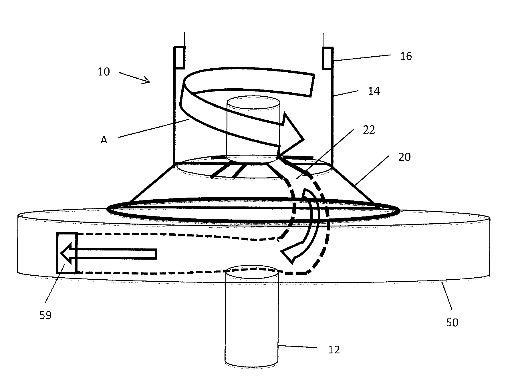
Figure 1 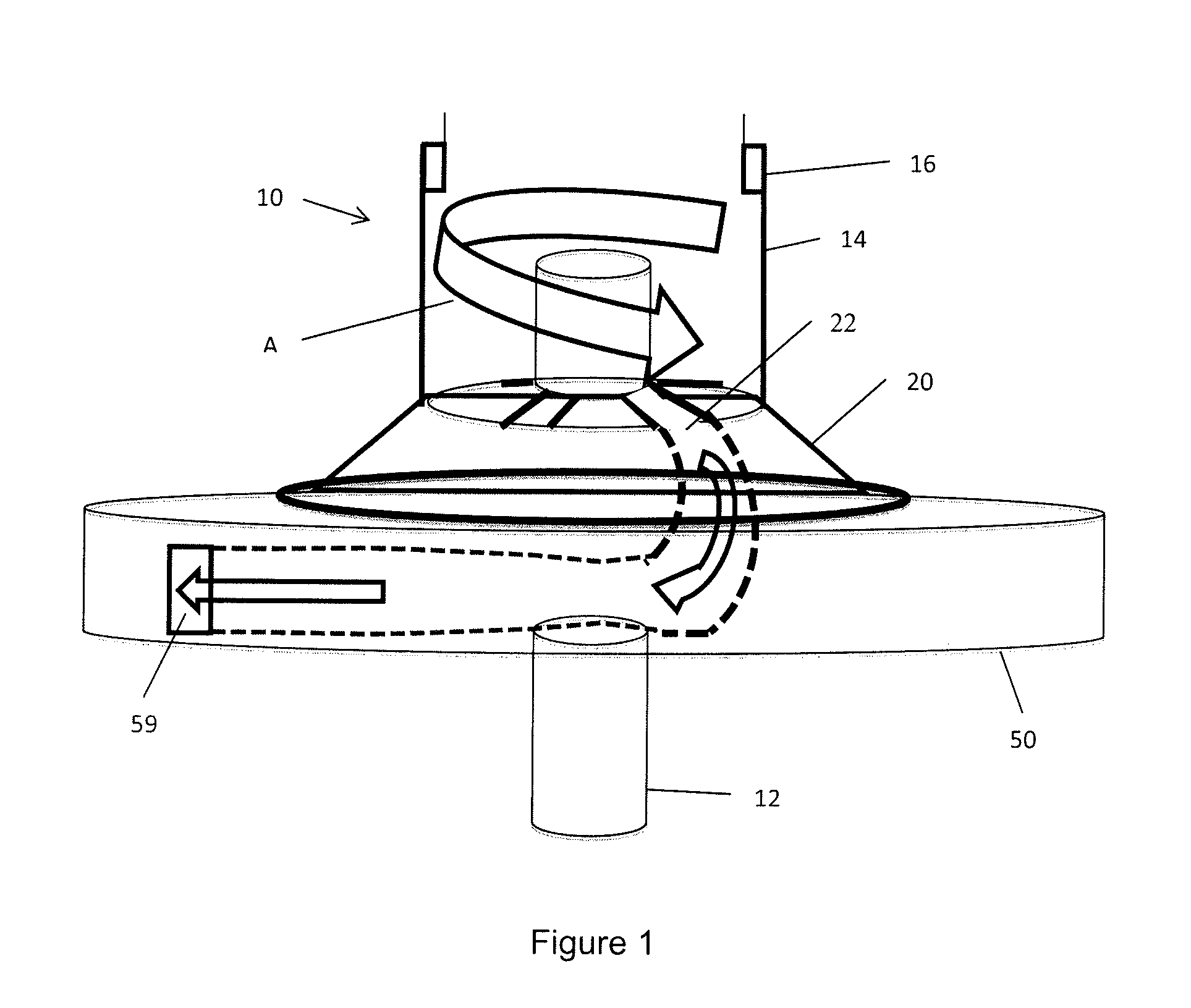
Figure 2 
Figure 3
Abstract
Description
CROSS-REFERENCE TO RELATED APPLICATIONS
[0001] This application claims benefit under 35 USC §119(e) to provisional applications 61 / 550,727, filed Oct. 24, 2011, to provisional application 61 / 636,964, filed Apr. 23, 2012 and to provisional application 61 / 703,041, filed Sep. 19, 2012, the contents of each of these applications is hereby incorporated by reference.FIELD OF THE INVENTION
[0002] The present invention relates to a high efficiency turbine capable of operating on low quality fuels. This turbine is a hybrid of the two main types of existing turbines: reaction and impulse.BACKGROUND OF THE INVENTION
[0003] In general, flow machines extract power from a fluid as the fluid flows from a higher energy state to a lower energy state. There are several types of flow machines, ranging from simple water wheels up to the most advanced gas turbines. Even though these machines have many differences, they all follow several basic laws.
[0004] Most notably, inventors from da Vinci to de Laval to Pe...
Examples
Embodiment Construction
[0055]As seen in FIG. 1, the hybrid turbine 10 has a solid shaft 12 supporting all components and powered by the turbine components. An intake conduit 14 supplies fluid from any suitable source, such as a combustor. The fluid has a vortex motion, shown by arrow A as the flow moves about solid shaft 12 and enters the top of impulse turbine 20 through intakes 22 extending radially from the shaft 12 about a top wall of the impulse turbine 20. The impulse turbine is shown with a conical sidewall, but the sidewall may by cylindrical.
[0056]The above system uses a single incoming flow from the combustor, progressing from the combustor to the rotor. For maximum power density, the flow can come from two combustors, or a split stream source, etc. In this case, the flow chamber size must be doubled. The net result is extremely high power density for aerospace and other limited work space applications. Guide vanes in the intake can direct the flow smoothly into the channel. Note that these guid...