
Power source apparatus
Patent Information
- Authority / Receiving Office
- US · United States
- Current Assignee / Owner
- Publication Date
- 2013-07-25
Smart Images
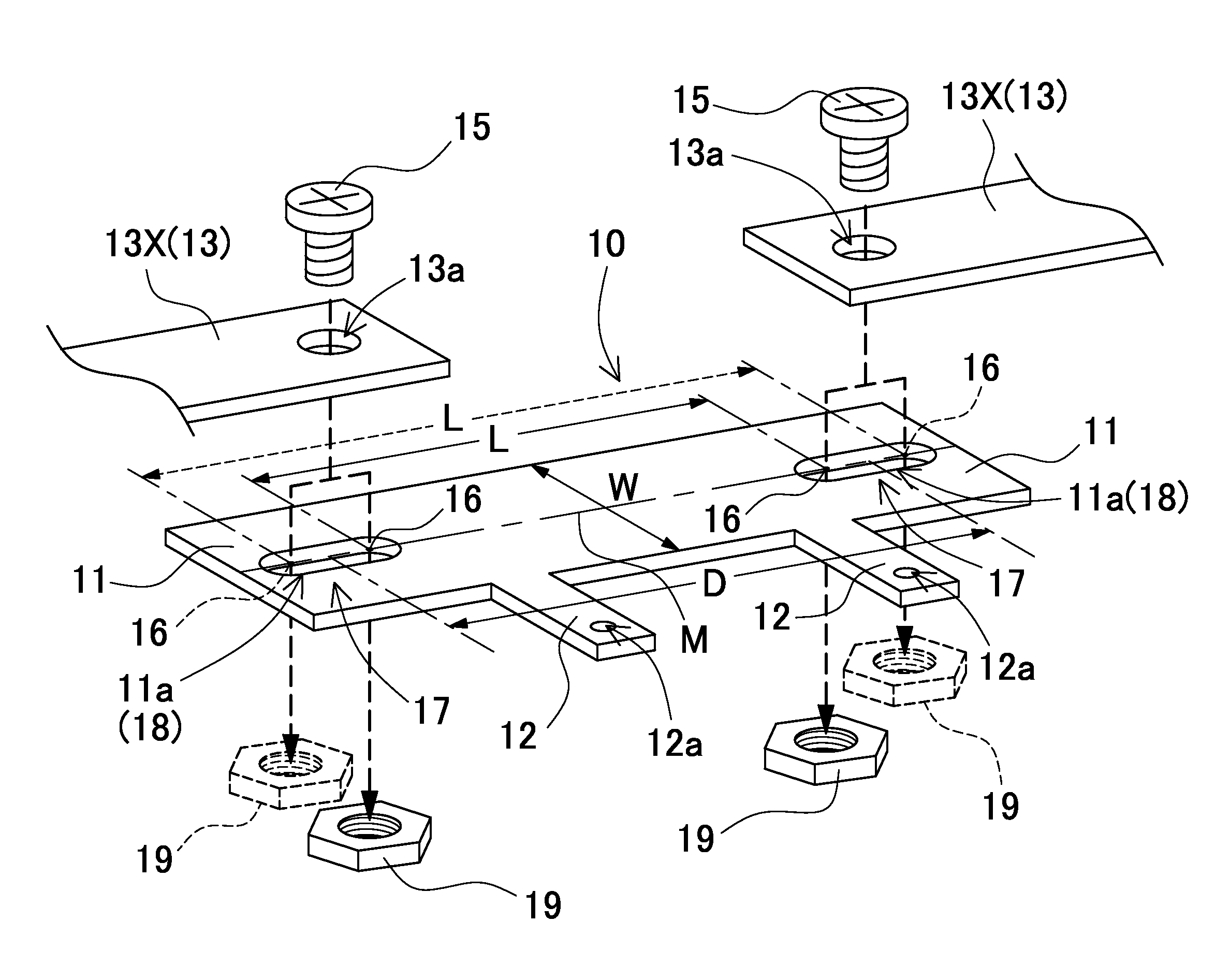
Figure 1 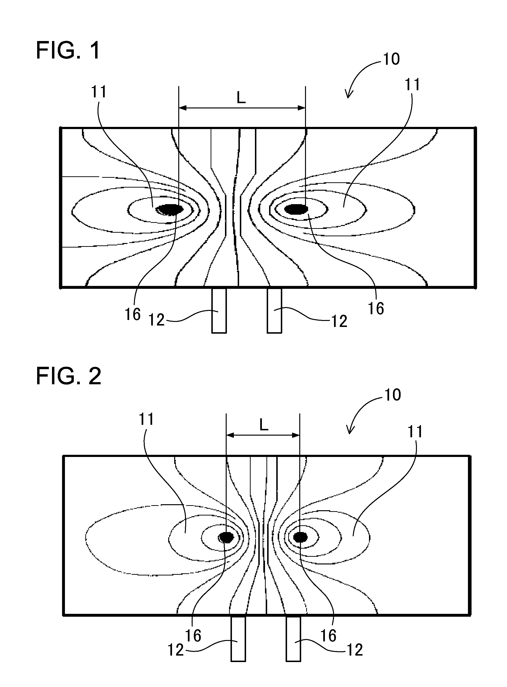
Figure 2 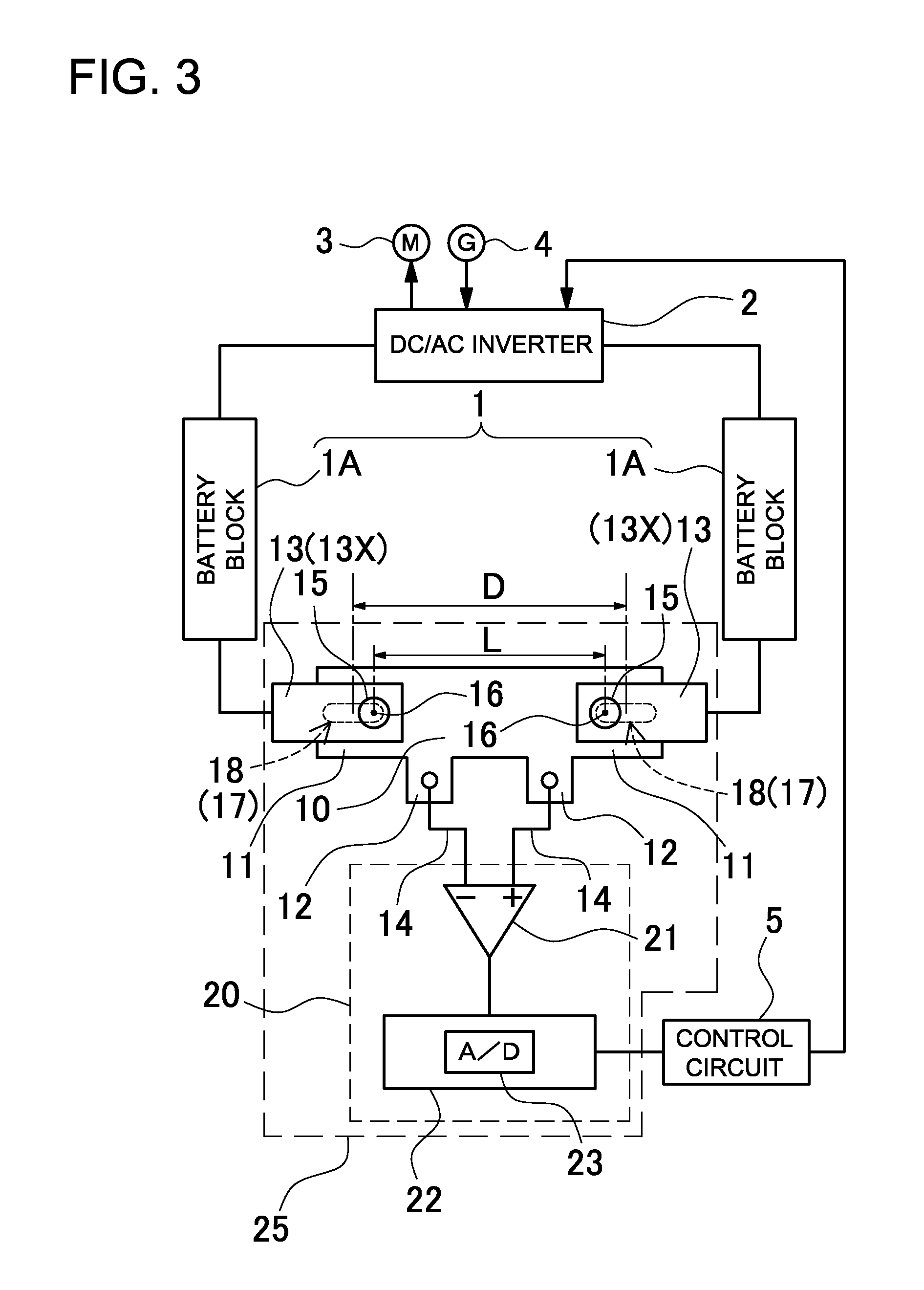
Figure 3
Abstract
Description
BACKGROUND OF THE INVENTION
[0001] 1. Field of the Invention
[0002] The present invention relates to a power source apparatus having a shunt resistor connected in series with the batteries to determine battery current by detecting the voltage induced across the resistor, and in particular to a power source apparatus optimally suited as a power source that is charged and discharged with high current such as a power source that supplies power to a motor to drive a vehicle.
[0003] 2. Description of the Related Art
[0004] A power source apparatus is equipped with current sensing to detect battery charging and discharging current. A power source apparatus with a current sensor can integrate current to compute remaining capacity, can control battery charging and discharging using the computed remaining capacity, and can prevent battery over-charging and over-discharging. Batteries have the characteristic that they degrade significantly due to over-charging and over-discharging. Accordingly, accur...
Examples
Embodiment Construction
[0026]The following describes embodiments of the present invention based on the figures. However, the following embodiments are merely specific examples of a power source apparatus representative of the technology associated with the present invention, and the power source apparatus of the present invention is not limited to the embodiments described below. Further, components cited in the claims are in no way limited to the components indicated in the embodiments.
[0027]Turning to FIG. 3, a vehicle power source apparatus carried on-board a hybrid vehicle (hybrid car, hybrid electric vehicle, HEV) or plug-in hybrid vehicle (PHV, plug-in hybrid electric vehicle, PHEV) is shown. However, the power source apparatus of the present invention can be used in any application charged and discharged with high current and is not limited only to automotive applications such as in a hybrid vehicle. The power source apparatus of the figure is provided with batteries 1 that supply power through a d...