
Display device and method for producing same
Patent Information
- Authority / Receiving Office
- US · United States
- Current Assignee / Owner
- Publication Date
- 2013-09-26
Smart Images
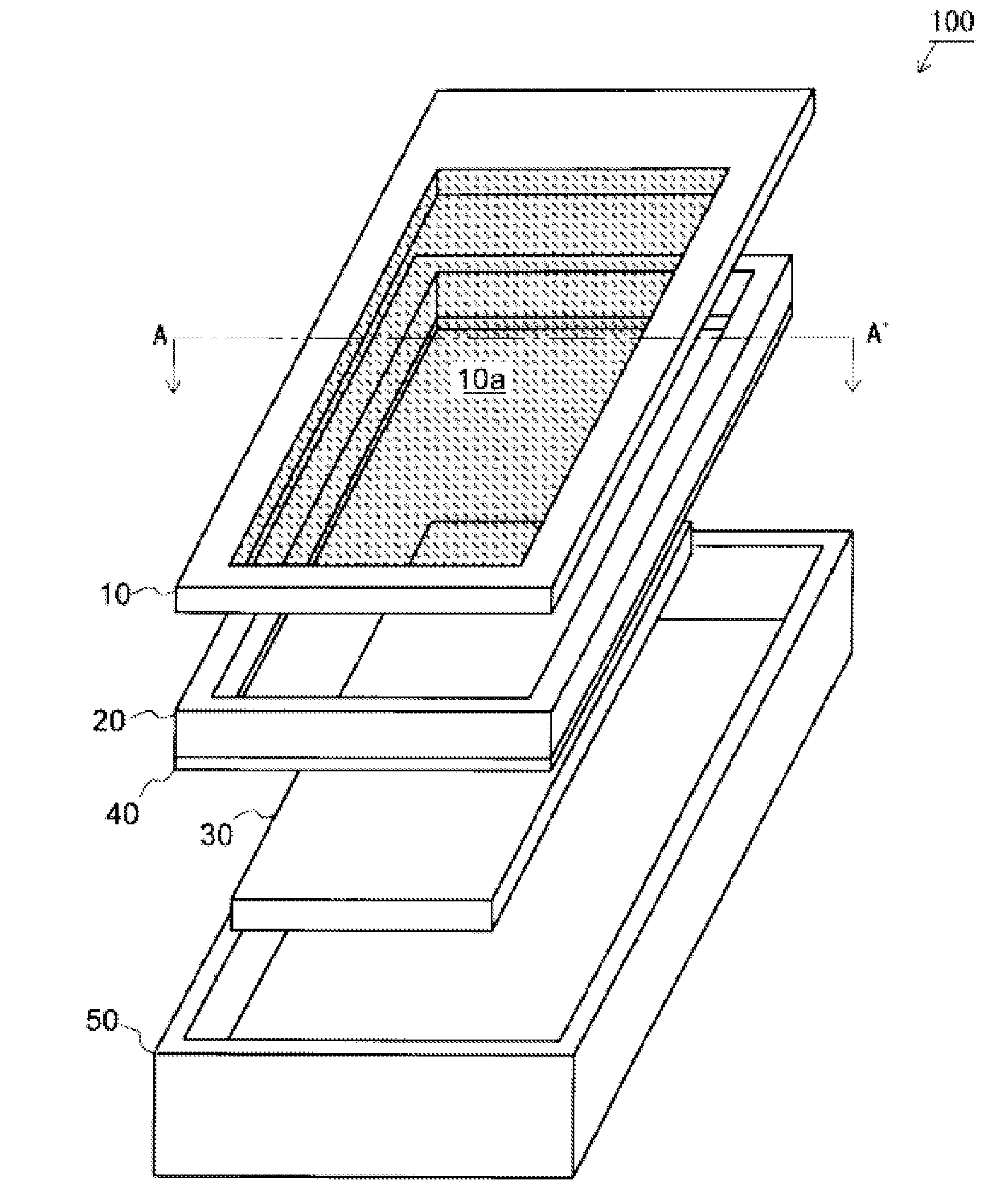
Figure 1 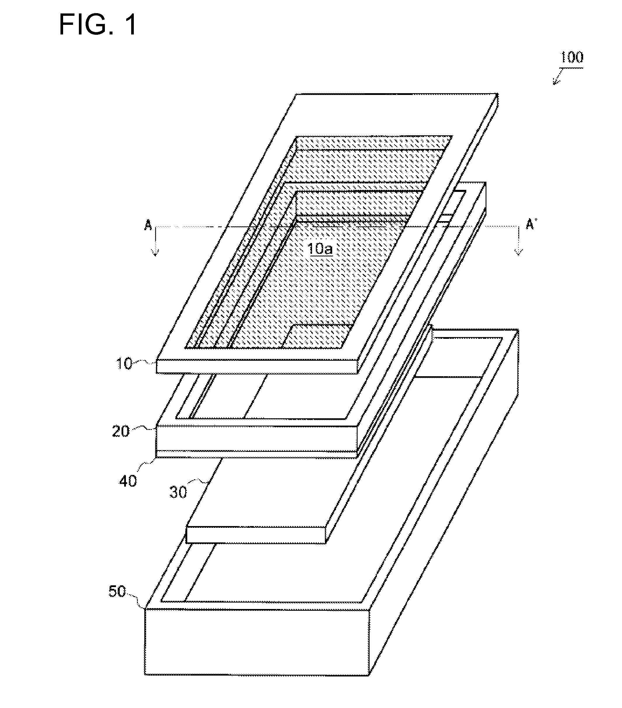
Figure 2 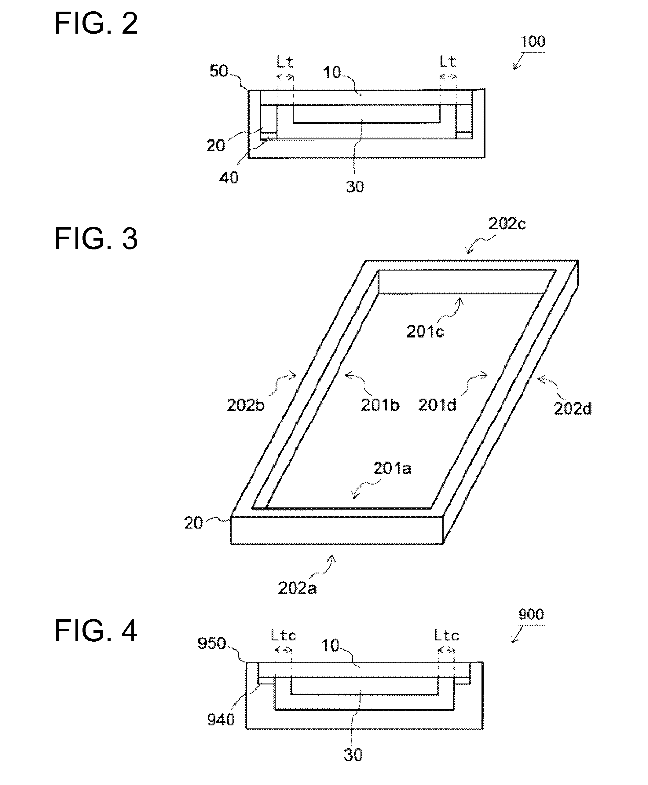
Figure 3
Abstract
Description
TECHNICAL FIELD
[0001] The present invention relates to a display device that displays an image and a method of manufacturing the same. More particularly, the present invention relates to a display device that is provided with a surface protector attached to a display surface, and a method of manufacturing the same.BACKGROUND ART
[0002] In recent years, display devices such as personal digital assistants that require operations including menu selections are increasingly provided with a touch panel. Through the touch panel, a user performs an operation such as selecting a desired menu by pressing the panel with a stylus or a finger in accordance with the display on the screen. For touch panels used in such personal digital assistants, various known types are employed such as a resistive type, a capacitive type, a photosensor type, and an infrared type, to detect a pressed position on the panel.
[0003] In most cases, display devices equipped with such a touch panel are provided with a surfa...
Examples
modification example 2
4.2 Modification Example 2
[0092]FIG. 7 is a schematic perspective view showing a structure of yet another modification example of the positioning frame shown in FIG. 3. In the positioning frame 23 shown in FIG. 7, the inner side faces 201c, 201d and the outer side faces 202c, 202d in the positioning frame 20 shown in FIG. 3 are entirely omitted.
[0093]Even when a portion of the frame member is omitted in this manner, by making the outer side face 232a shown in FIG. 7 and a corresponding outer side face of the top window 10 lie on the same plane, and by making the outer side face 232b in the positioning frame 23 and a corresponding outer side face of the top window 10 lie on the same plane, the positioning frame 23 can be bonded to the top window 10 accurately with ease so as not to protrude to the outside.
[0094]Also, by positioning the liquid crystal module 30 so as to make contact with the inner sides of the positioning frame 23 (that is, the inner side faces 231a and 231b), the liq...
modification example 3
4.3 Modification Example 3
[0097]FIG. 8 is a simplified cross-sectional view showing a configuration of a display device of Modification Example 3. A display device 101 shown in FIG. 8 further includes an adhesive agent 45, in addition to the same constituting elements as those in the display device 100 shown in FIG. 2, which are provided with the same reference characters, and the manufacturing process thereof differs from that of the display device 100.
[0098]That is, in the second manufacturing step above, the liquid crystal module 30 is inserted in the positioning frame 20, and is bonded to the top window 10. However, in this example, before being bonded to the top window 10, the liquid crystal module 30 is inserted in the positioning frame 20 first, and the positioning frame 20 is bonded to the liquid crystal module 30 by the adhesive agent 45.
[0099]Next, in a manufacturing step corresponding to the first manufacturing step above, the positioning frame 20 is bonded to the top win...
modification examples
4.4 Other Modification Examples
[0102]In the above embodiments and modification examples, components were bonded through a known adhesive material such as a double-sided adhesive tape or an adhesive agent, but this is only an example. Any configuration may be employed as long as the respective components are fixed to each other, and the respective components may be fixed to each other by using a known method such as using a bolt, a screw, or a pin. The configuration using an adhesive material is preferable since it is a simple and reliable method to fix respective surfaces to each other.
[0103]In the above embodiments and modification examples, the liquid crystal module 30 was configured to include a glass substrate, but the substrate may be made of other materials such as plastic that are undesirable to make direct contact with the case 50. Also, a known display module using an organic EL element or the like may be used instead of the liquid crystal module 30 using a liquid crystal e...