
Asymmetrical toothed wheel
Patent Information
- Authority / Receiving Office
- US · United States
- Current Assignee / Owner
- Publication Date
- 2014-12-25
Smart Images
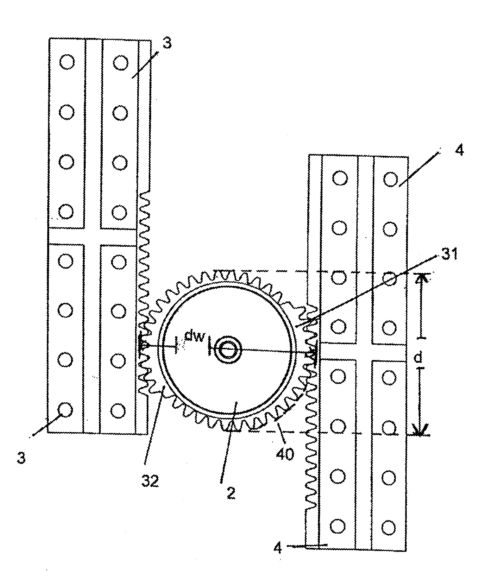
Figure 1 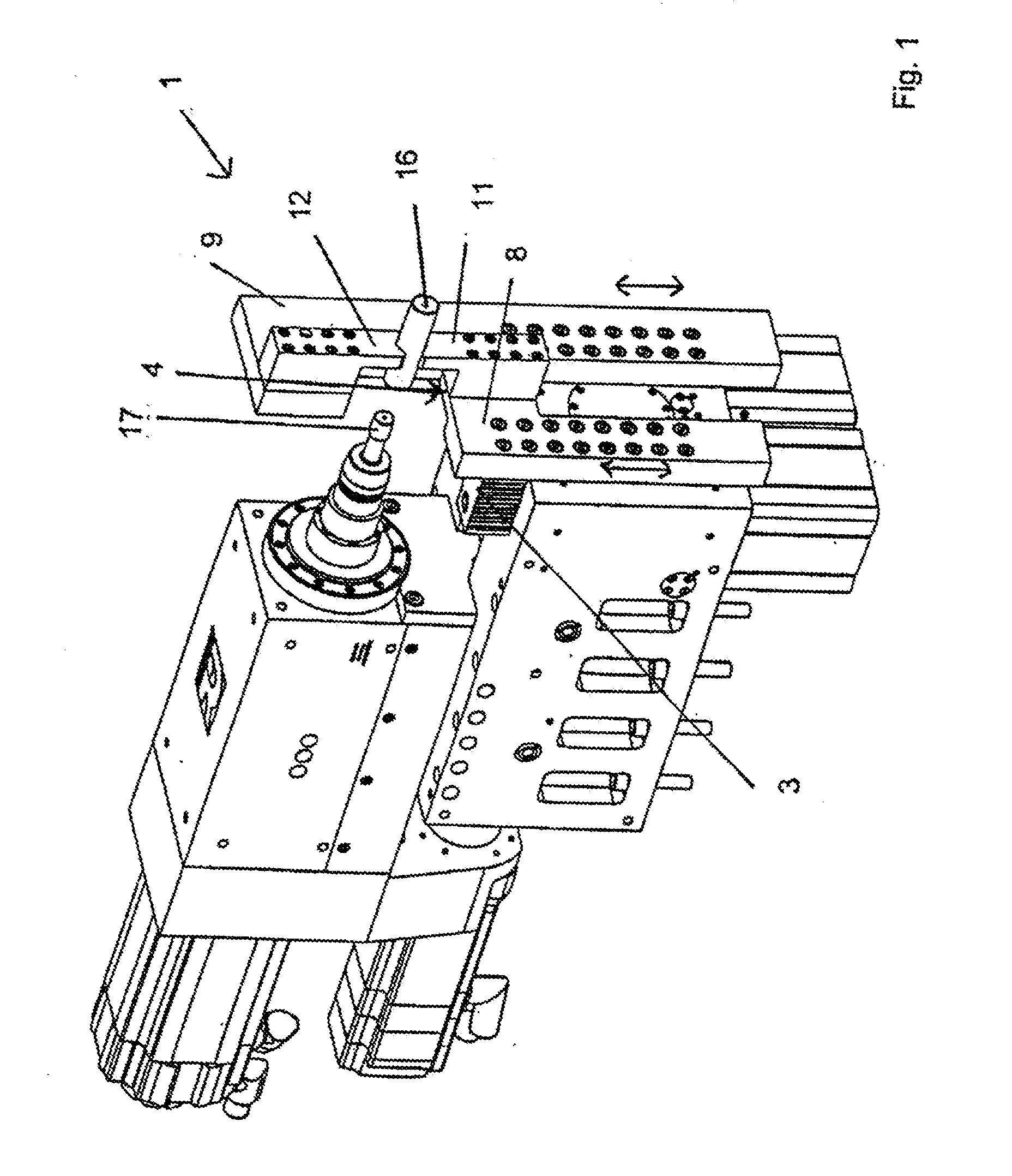
Figure 2 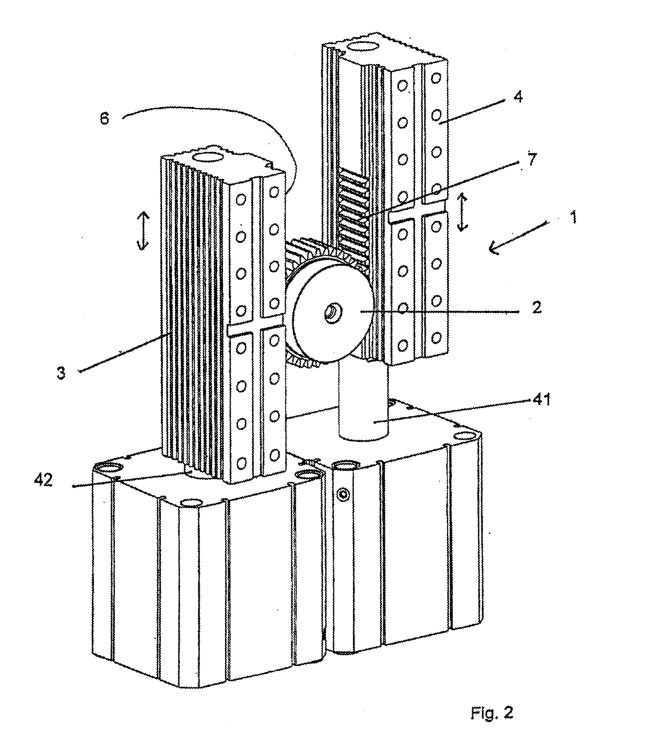
Figure 3
Abstract
Description
CROSS REFERENCE TO RELATED PATENT APPLICATIONS
[0001] This patent application is filed herewith for the U.S. National Stage under 35 U.S.C. §371 and claims priority to PCT application PCT / EP2012 / 077044, with an international filing date of Dec. 28, 2012. The contents of this application are incorporated in their entirety herein.BACKGROUND OF THE INVENTION
[0002] The invention relates to a device with supports capable of being moved with respect to each other according to the preamble of Claim 1.
[0003] The device is known as part of a clamping device for elongate profile sections in the prior art, for example from DE 1 463 226 A.
[0004] The known clamping devices for tube sections have separate clamping jaws by which the tube section cut to length can be positioned in a fixed manner with respect to a machining tool, for example a bevelling head. Although clamping tools of this type clamp sufficiently firmly the tube section cut to length, they are nevertheless inadequate in their precision....
Examples
Embodiment Construction
[0022]FIG. 1 shows the part of a clamping device 1 for clamping, in particular, metallic tube ends 16. The clamping device 1 is part of a profile-sawing machine (not shown). Profile-sawing machines allow sections to be sawn off from, in particular, metallic tubes or metallic solid profiles as a special form of the elongate profiles. The sawn-off profile sections can then be further machined on the ends thereof with machining apparatus in the machining procedures following the sawing. The further machining can take place for example in a bevelling process by a bevelling tool 17 or by centring boring by means of a centring bore, in particular in the case of solid profiles. The requirements for the precision of the machining are very high, so that for example during the bevelling of tube section ends the eccentricity of the bevel with respect to the external face of the material on account of clamping errors should amount at most to from 0.01 to 0.05 mm depending upon requirements.
[002...