
Encapsulated quantum dots in porous particles
Patent Information
- Authority / Receiving Office
- US · United States
- Current Assignee / Owner
- Publication Date
- 2016-03-24
Smart Images
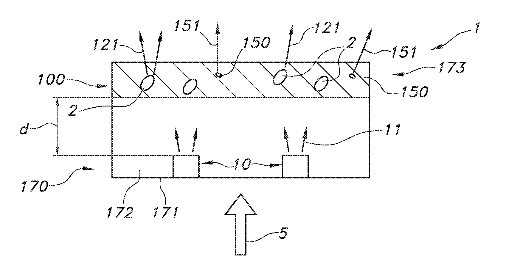
Figure 1 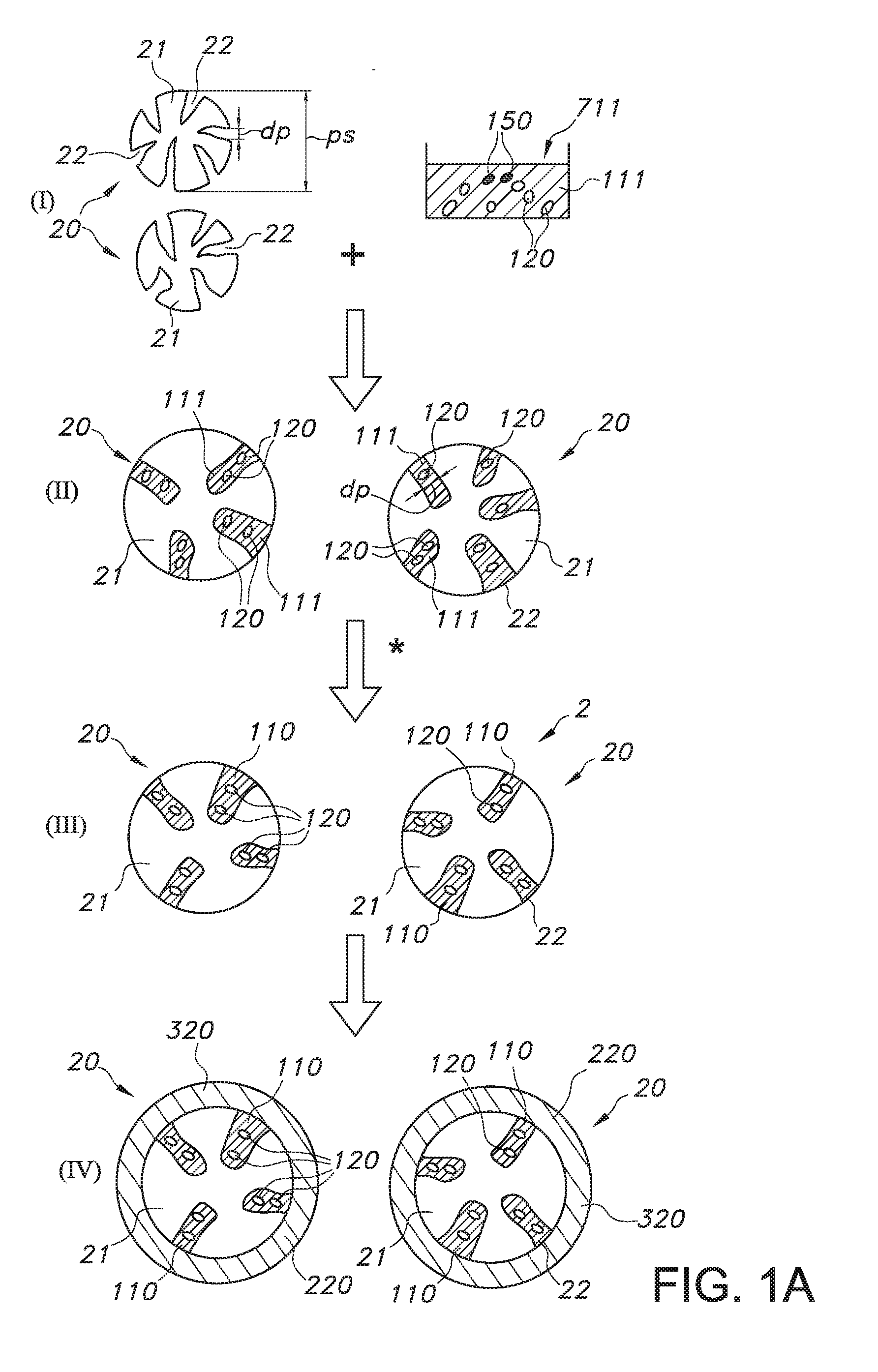
Figure 2 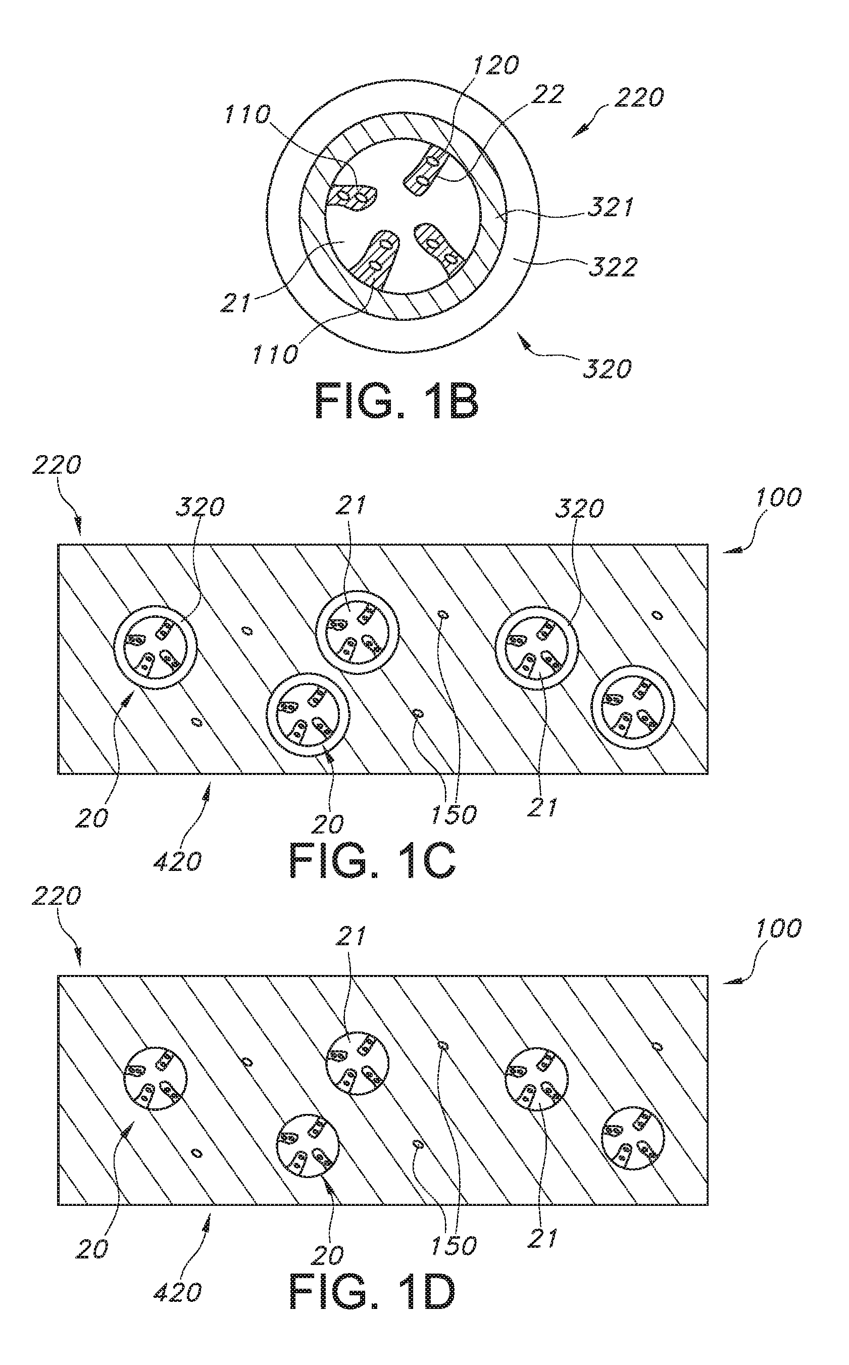
Figure 3
Abstract
Description
FIELD OF THE INVENTION
[0001] The invention relates to a (particulate) luminescent material, as well as to a production process for such (particulate) luminescent material. The invention further relates to a wavelength converter and lighting device comprising such (particulate) luminescent material.BACKGROUND OF THE INVENTION
[0002] Quantum dot (QD) based lighting is known in the art. WO2012021643, for instance, describes systems and methods that relate to quantum dot structures for lighting applications. In particular, quantum dots and quantum dot containing inks (comprising mixtures of different wavelength quantum dots) are synthesized for desired optical properties and integrated with an LED source to create a trichromatic white light source. The LED source may be integrated with the quantum dots in a variety of ways, including through the use of a small capillary filled with quantum dot containing ink or a quantum dot containing film placed appropriately within the optical system. T...
Examples
example 1
Preparation of Impregnated Particles
[0191]Trisoperl particles were impregnated according as follows: 1 gram of 5% wt dispersion of Crystalplex QDs in heptanes was added to IBMA / HDDA (5 g). This results in a 1% wt dispersion QDs in IBMA / HDDA, to which 1 gram of PSPs were added, and 0.5% wt photoinitiator (irgacure 184). The powder-acrylate mixture was put on a Buchner funnel, and filtrated for a few minutes in the glovebox. After filtration the powder was cured for 4 minutes with UV light in the glovebox. This results in a sticky powder, which was converted into a loose powder of individual PSPs by dispersing it in toluene and giving it a 15 minute US treatment in a close vial, hence no contact with ambient air. Next, the toluene was removed in the glovebox, by decanting, followed by evacuation of a few hours to remove all toluene. FTIR measurements show that the acrylic has a 95% conversion rate, which means a nearly complete curing of the acrylate. A subset of these particles was m...
example 2
Plasma Enhanced ALD on Impregnated PSP
[0192]50 mg of the impregnated PSP (batch 1) was spread out over a silicon wafer (outside the glovebox), and inserted into the Emerald chamber (for plasma enhanced ALD) of an ASM dual chamber ALD system. A 50 nm alumina layer was applied using the plasma-enhanced ALD process at 100 C, using TMA (trimethylaluminium) and O2 as reactive gasses. After deposition, the powder was harvested and mixed into Ebecryl 150 (with 1% wt irgacure 184) to make cured films of the ALD-coated PSP's in a secondary matrix. As described above in example 1, reference samples of the same impregnated PSP's without ALD were also made, in addition to films of plain QDs in IBMA / HDDA (no impregnation). In all cases, the samples consisted of a 100 um acrylic layer, in between two glass plates. The QE of the ALD-coated PSP's using plasma enhanced ALD (called sample ALD-a from here on) had a QE of 50%, which is the same as before ALD coating (batch 1, 52%). The ALD coating thus...
example 3
Thermal ALD@150 C on Impregnated PSP
[0200]30 mg of the impregnated PSP (batch 1) was spread out over a silicon wafer (outside the glovebox), and inserted into the Pulsar chamber (for thermal ALD) of an ASM dual chamber ALD system. A 50 nm alumina layer was applied using the thermal ALD process at 150 C, using TMA (trimethylaluminium) and O3 as reactive gasses. After deposition, the powder was harvested and mixed into Ebecryl 150 (with 1% wt irgacure 184) to make cured films of the ALD-coated PSP's in a secondary matrix. The QE of the ALD-coated PSP's using thermal ALD at 150° C. (called sample ALD-b from here on) had a QE of 31%, which is a drop of 20% compared to before ALD coating (batch 1, QE of 52%).
[0201]A small part of the thermal ALD coated particles from ALD-b was used to make cross-sections and investigate in SEM. FIG. 7a shows a SEM image of PSP's with ALD-b coating. In the prepared Schliffs (cross-sections) some of the particles were not fully embedded in the epoxy carrie...