
Rotating electric machine stator
Patent Information
- Authority / Receiving Office
- US · United States
- Current Assignee / Owner
- Publication Date
- 2016-11-17
Smart Images
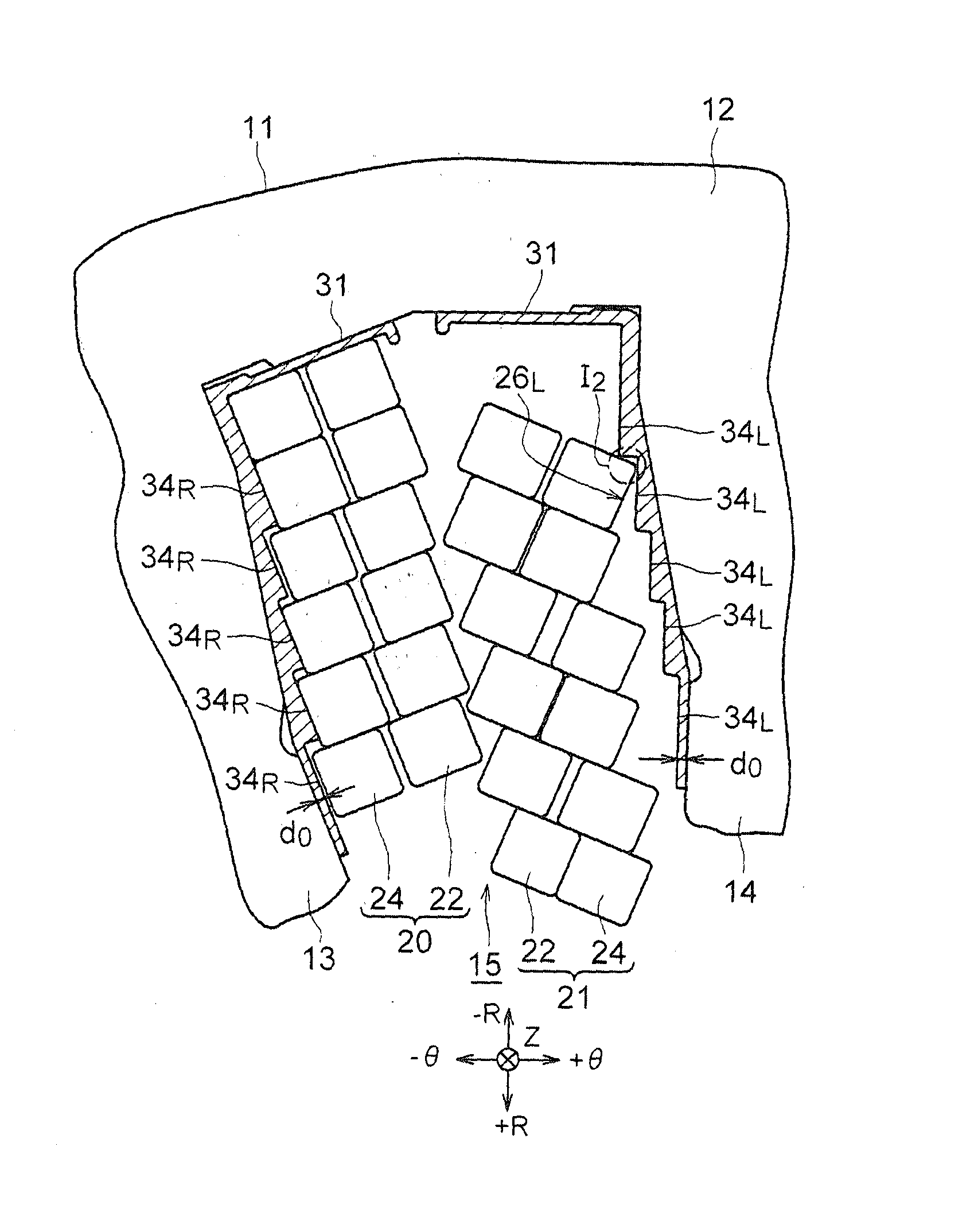
Figure 1 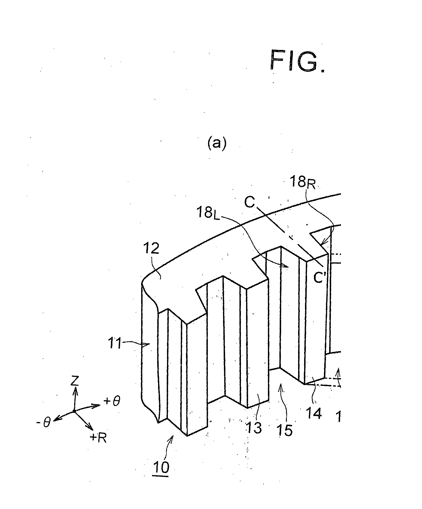
Figure 2 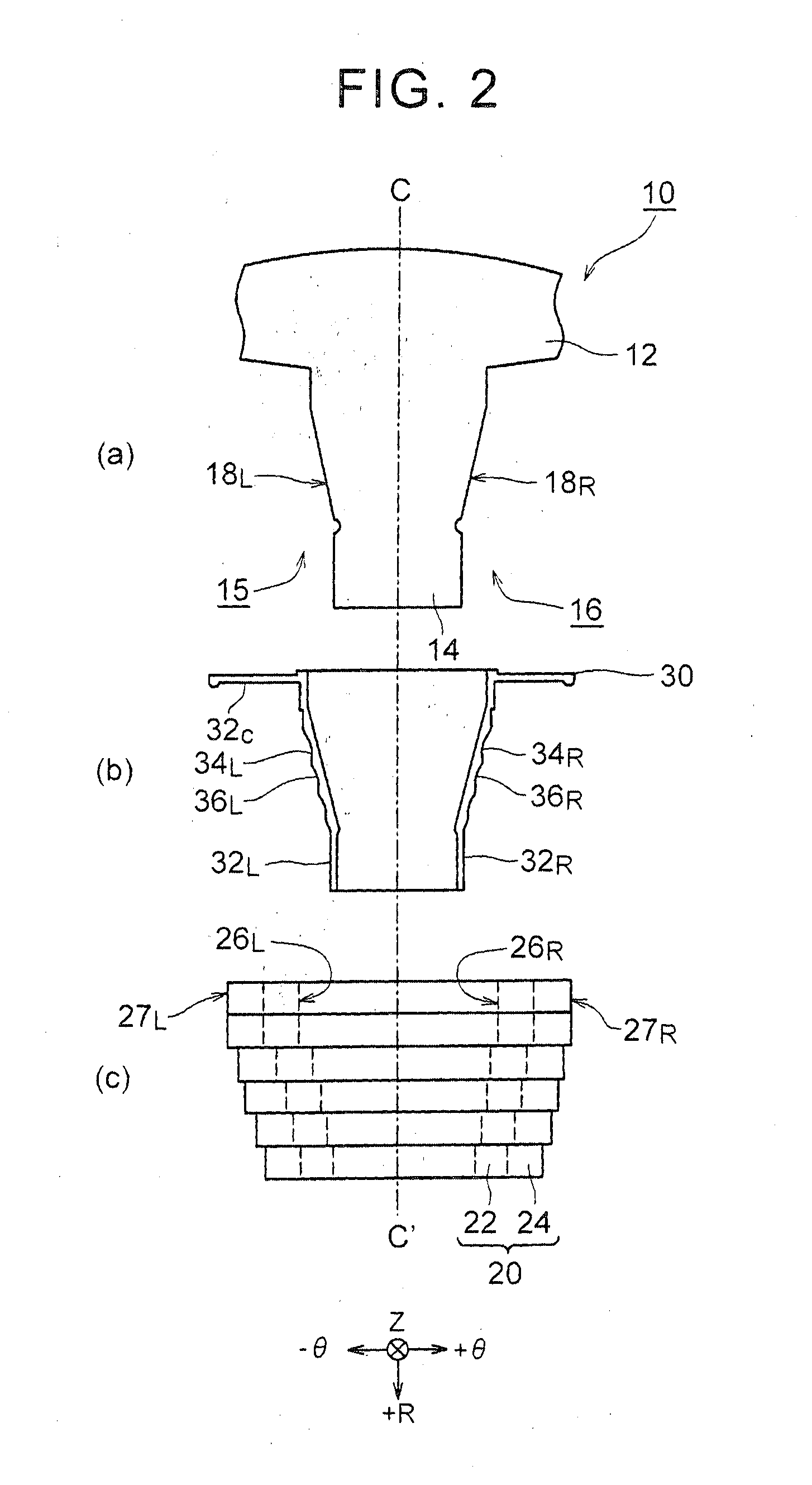
Figure 3
Abstract
Description
BACKGROUND OF THE INVENTION
[0001] 1. Field of the Invention
[0002] The present invention relates to a rotating electric machine stator, and more particularly, to a rotating electric machine stator in which coils are wound via insulators.
[0003] 2. Description of Related Art
[0004] When coils of a rectangular wire are wound via insulators, the insulators are preferably as thin as possible in order to improve the space factor of the windings as long as the insulating performance of the insulators is ensured.
[0005] Japanese Patent Application Publication No. 2012-222944 (JP 2012-222944 A) discloses a stator in which rectangular wires are wound around teeth that protrude inward from a yoke portion of a stator core via insulators. In the stator, the thickness of the insulators is varied depending on the relative positional relationship between the rectangular wires and the teeth.
[0006] It is stated in Japanese Patent Application Publication No. 2013-162565 (JP 2013-162565 A) that concentrated win...
Examples
Embodiment Construction
[0026]An embodiment of the present invention is described below in detail with reference to the drawings. The dimensions, shapes, materials and so on that are described below are shown for illustrative purposes and may be changed as needed depending on the design of the rotating electric machine stator and so on. In addition, in the following, the same elements are designated in all the drawings by the same reference numerals and redundant description is not repeated.
[0027]FIG. 1 and FIG. 2 are diagrams that illustrate the configuration of a rotating electric machine stator 10 that is used in a rotating electric machine that is mounted in a vehicle. In the following, the rotating electric machine stator 10 is referred to as “stator 10” unless otherwise stated. In FIG. 1, (a) is a perspective view of a stator core 11, and (b) is a perspective view of an insulator 30 that is fitted on each tooth 14 of the stator core 11 that is shown in (a). In FIG. 2, (a) is a top view of the tooth 1...