
Personal evaporative cooling apparatus
Patent Information
- Authority / Receiving Office
- US · United States
- Current Assignee / Owner
- Publication Date
- 2017-01-26
Smart Images
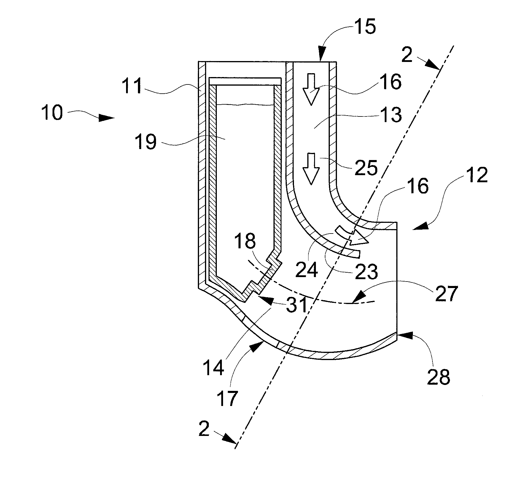
Figure 1 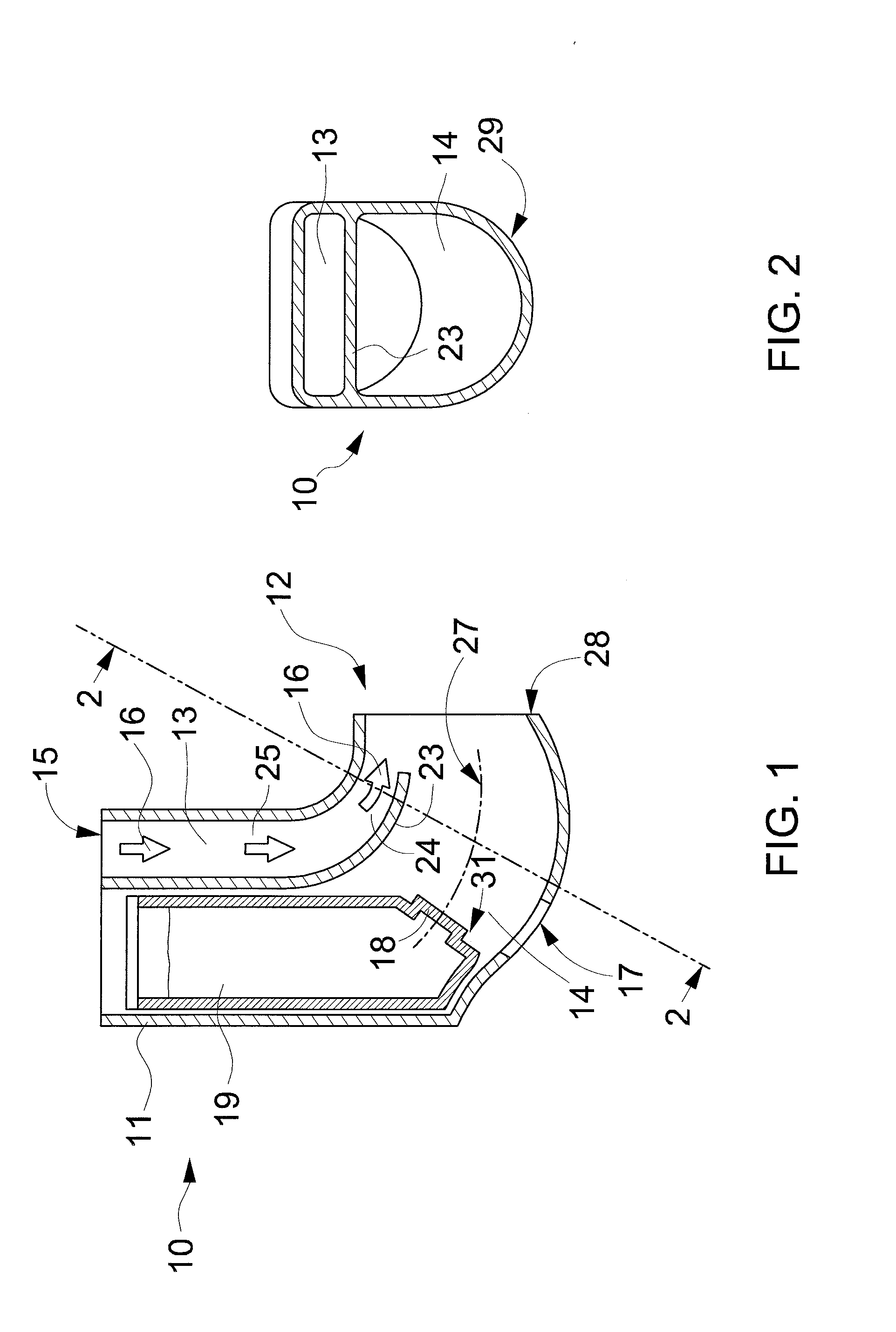
Figure 2 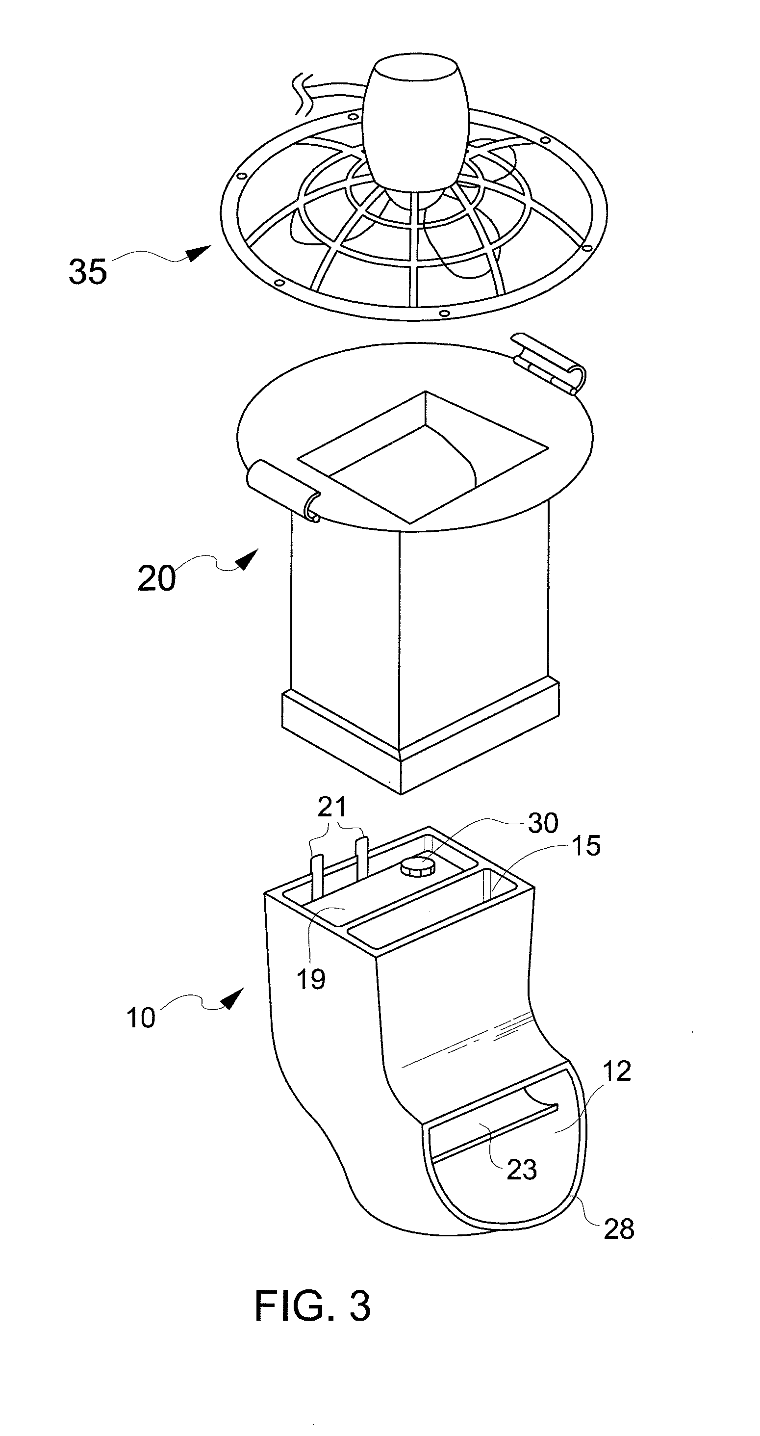
Figure 3
Abstract
Description
TECHNICAL FIELD
[0001] The present invention relates generally to personal cooling apparatuses employing the evaporative cooling principle.BACKGROUND OF THE INVENTION
[0002] It is known in the art to provide a self-contained evaporative personal cooling apparatus that can be hand-held or, for instance, hung about a user's waist or neck. Such apparatuses comprise a water mister and a blower and often provide a two-stage cooling effect. In the first stage, flash evaporation of a finely divided water mist cools that air before it is blown over the skin, while in the second the air flow that carries moisture to the skin also increases the rate of evaporation of this moisture from the skin, for a wind chill effect.
[0003] U.S. Pat. No. 6,371,388 describes a misting blower, secured about the waist of the user, in which a fine spray of water is provided adjacent to the blower's exhaust nozzle, such that the air and water spray mixing and cooling primarily takes place outside the nozzle outlet. H...
Examples
first embodiment
[0031]Referring to FIGS. 1 and 2, an evaporative cooler may be a hand-held cooling apparatus that, when upright (as shown) outputs a generally horizontal outlet stream of cool air and entrained water droplets for personal cooling. The apparatus comprises a first housing 10 having an upper portion 11 ergonomically designed to be conveniently cupped in the palm of a hand, allowing the user to then move the entire apparatus so as to direct the stream from the induction nozzle 12 back toward the user to a point of use.
[0032]The housing 10 may be an assembly of rigid substantially impermeable walls of polymeric material, formed as by moulding, so as to define a primary passage 13 and an adjacent secondary passage 14. The primary passage 13 extends from a supply port 15 to the induction nozzle 12 for delivering a primary air stream 16 to the induction nozzle 12. The secondary passage 14 extends from an ambient air inlet 17 to the induction nozzle 12.
[0033]An atomiser 18 is disposed in the...
fourth embodiment
[0046]FIGS. 7 and 8 illustrate third and fourth embodiment of the cooling apparatus and, in particular, show further preferred alternative forms of the secondary passage 214, 314. In both embodiments, the ambient air inlets 117 and induction nozzles 212, 312 are generally disposed at longitudinally opposing ends of secondary passages 214, 314 that have centrelines 127, 227. The atomiser 18 is disposed on a lower side of the tank 119, above a base 80 of the tank 119, and generally transversely of the centrelines 127, 227. The ambient air inlets 117 are located below the base 80. The secondary passages 214, 314 comprise, extending in their longitudinal direction from the inlet 17, an inlet throat portion 81, 181 below the base 80 that joins an enlarged outlet portion 82, 182 that extends to the induction nozzle 212, 312. In this manner, a dogleg is provided in both secondary passages 214, 314, where the inlet throat portion 81 meets the outlet portion 82, 182.
[0047]As shown in FIG. 7,...