
Ion transport apparatus and mass spectrometer using the same
a mass spectrometer and ion transport technology, applied in the direction of electron/ion optical arrangement, tube electrostatic deflection, particle separator tube details, etc., can solve the problems of difficult to ensure a complex structure or electrode shape, and significant noise of neutral particles in ion detectors. achieve high ion transmission efficiency, reliably remove undesired neutral particles, simple structure and configuration
Patent Information
- Authority / Receiving Office
- US · United States
- Current Assignee / Owner
- Publication Date
- 2017-05-25
- Estimated Expiration
- Not applicable · inactive patent
Smart Images
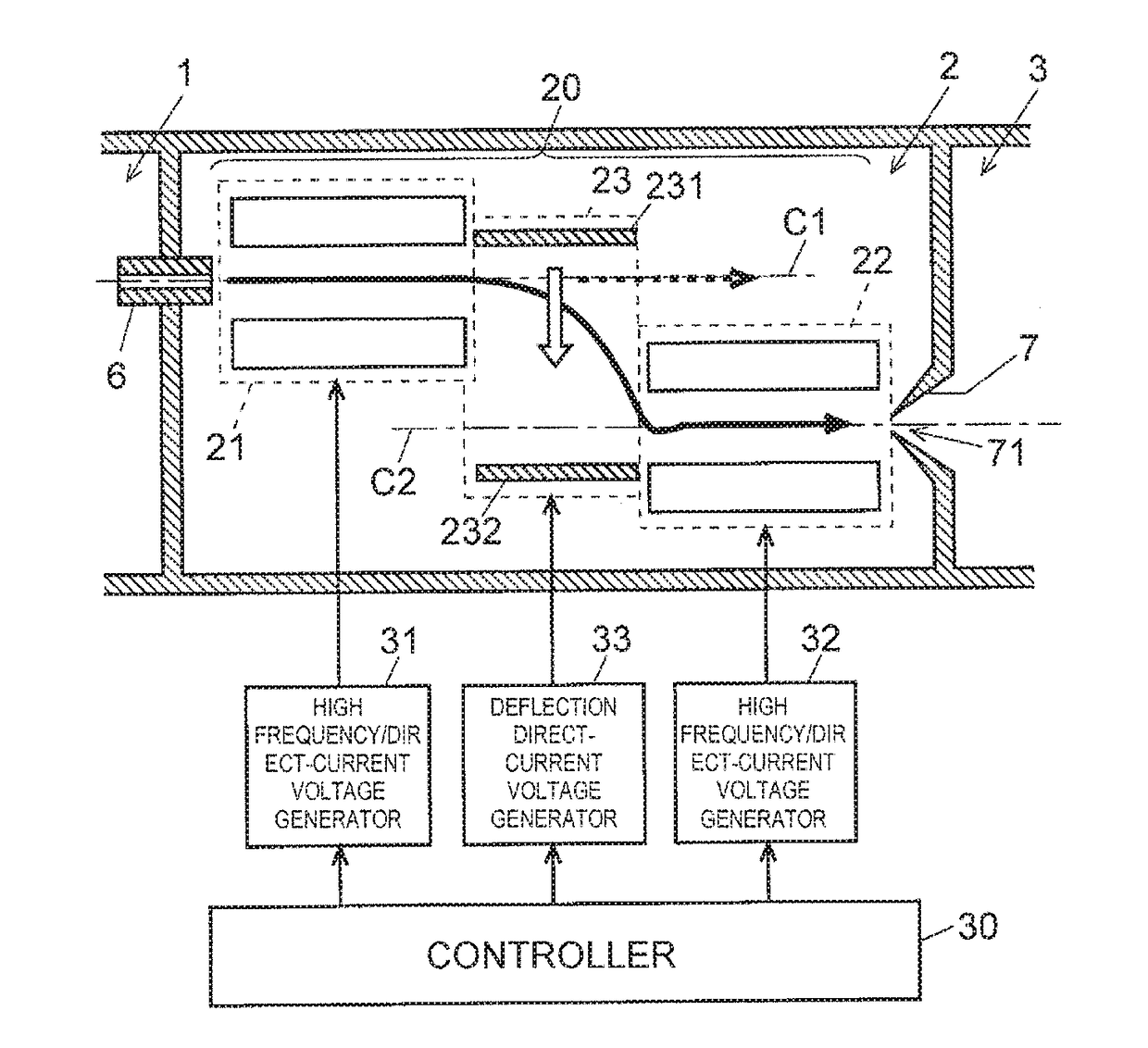
Figure 1 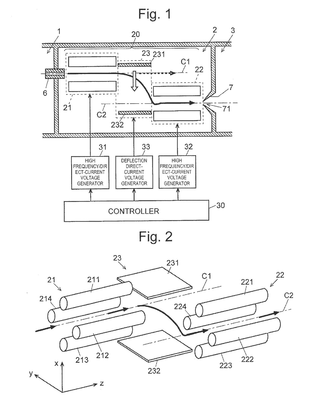
Figure 2 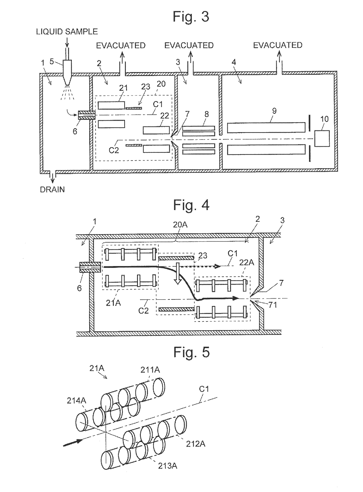
Figure 3
Abstract
Description
TECHNICAL FIELD
[0001] The present invention relates to an ion transport apparatus for transporting ions while trapping them, and more specifically, to an ion transport apparatus suitable for a mass spectrometer including an ion source for ionizing a sample in an atmosphere having a comparatively high level of gas pressure which is close to atmospheric pressure, such as an electrospray ionization mass spectrometer, atmospheric pressure chemical ionization mass spectrometer, and radio-frequency inductively coupled plasma ionization mass spectrometer. It also relates to a mass spectrometer using such an ion transport apparatus.BACKGROUND ART
[0002] In a mass spectrometer using an atmospheric pressure ion source, such as an electrospray ionization (ESI), atmospheric pressure chemical ionization (APCI) or atmospheric pressure photoionization (APPI), the ionization chamber is maintained at a substantially atmospheric pressure, whereas the analysis chamber, which contains a mass separator (e....
Examples
first embodiment
[0056]An atmospheric pressure ionization mass spectrometer, which is a mass spectrometer using one embodiment (a first embodiment) of an ion transport apparatus according to the present invention, is described. FIG. 1 is a schematic configuration diagram of an ion transport optical system in the first embodiment, FIG. 2 is a schematic perspective view of an electrode unit of the ion transport optical system in the first embodiment, and FIG. 3 is a schematic configuration diagram of an atmospheric pressure ionization mass spectrometer using the ion transport optical system in the first embodiment.
[0057]In FIG. 3, an ionization chamber 1 is maintained at a substantially atmospheric pressure, and an analysis chamber 4 is maintained at a high degree of vacuum by evacuation using a high-performance vacuum pump (normally, a combination of a turbo-molecular pump and a rotary pump), which is not illustrated. Between the ionization chamber 1 and the analysis chamber 4, a first intermediate v...
second embodiment
[0074]In place of the front-stage and rear-stage quadrupole ion guides 21 and 22 in the off-axis ion transport optical system in the first embodiment, quadrupole array ion guides having rod electrodes replaced with virtual rod electrodes consisting of plate electrodes, or multipole array ion guides other than quadrupole ones can be used. FIG. 4 illustrates the schematic configuration of an off-axis ion transport optical system 20A in a second embodiment using quadrupole array ion guides. FIG. 5 is a schematic perspective view of an electrode unit of a quadrupole array ion guide. In FIG. 4, the same components as those of the off-axis ion transport optical system in the first embodiment are denoted by the same reference signs.
[0075]In the second embodiment, a front-stage quadrupole array ion guide 21A and a rear-stage quadrupole array ion guide 22A both include virtual rod electrodes each of which consists of four disk-shaped electrodes. In FIG. 5, four virtual rod electrodes 211A, 2...
third embodiment
[0080]FIG. 7 is a schematic configuration diagram of an off-axis ion transport optical system 20B in a third embodiment. In this embodiment, a quadrupole ion guide 21 is used as a front-stage ion transport unit, and a radio-frequency carpet 22B is used as a rear-stage ion transport unit. FIG. 8 is a schematic perspective view of an electrode unit of this radio-frequency carpet 22B.
[0081]The radio-frequency carpet 22B is composed of a number of (five in this embodiment) ring electrodes 22B1, 22B2, 22B3, 22B4, and 22B5 disposed concentrically. High-frequency voltages +V cos ωt and −V cos ωt are applied to the ring electrodes neighboring each other in a radial direction, for example, to the ring electrodes 22B1 and 22B2, respectively, where the high-frequency voltages +V cos ωt and −V cos ωt have the same amplitude and frequency but have phases inverted from each other. Specifically, +V cos ωt is applied to some of the ring electrodes alternately positioned in the radial direction (the...