
Light emitting device
Patent Information
- Authority / Receiving Office
- US · United States
- Current Assignee / Owner
- Publication Date
- 2021-12-09
Smart Images
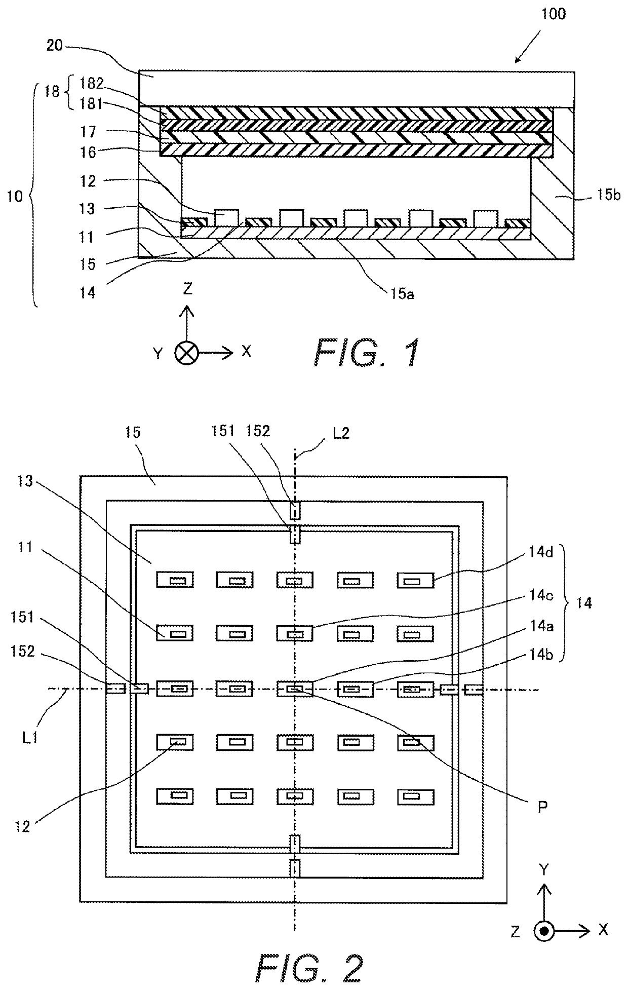
Figure 1 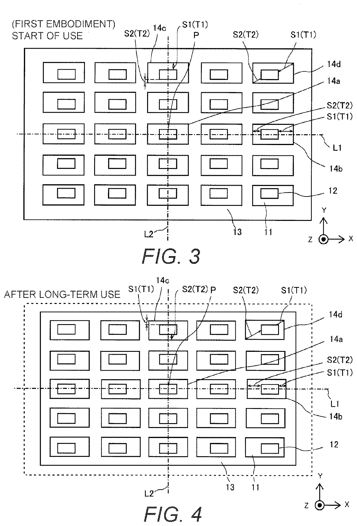
Figure 2 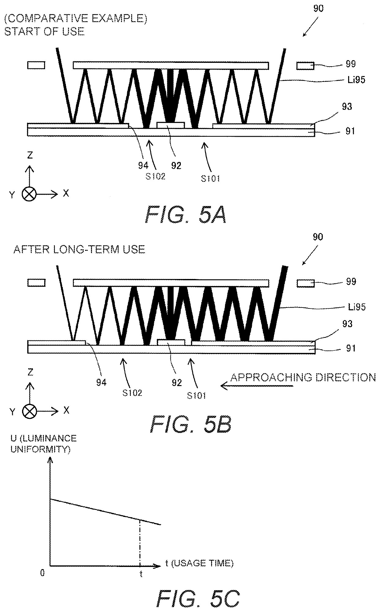
Figure 3
Abstract
Description
CROSS-REFERENCE TO RELATED APPLICATIONS
[0001] This application claims priority to Japanese Patent Application No. 2020-098847 filed on Jun. 5, 2020. The entire disclosure of Japanese Patent Application No. 2020-098847 is hereby incorporated herein by reference.BACKGROUNDField of the Invention
[0002] This invention generally relates to a light emitting device. More specifically, the present invention relates to a light emitting device equipped with a substrate, a plurality of light emitting elements and a reflective sheet.Background Information
[0003] Some light emitting devices are equipped with a substrate, a plurality of light emitting elements, and a reflective sheet (see Japanese Laid-Open Patent Application Publication No. 2011-181219 (Patent Literature 1), for example).
[0004] The light emitting device described in Patent Literature 1 above uses a reflective sheet with a plurality of apertures formed at positions of the light emitting elements. As a material of the reflective sheet, ...
Examples
first embodiment
[0033](Configuration of Light Emitting Device)
[0034]Referring to FIGS. 1 to 3, the configuration of a display device 100 including a light emitting device 10 according to a first embodiment will be described.
[0035]As shown in FIG. 1, the display device 100 has the light emitting device 10 and a display panel 20. The light emitting device 10 is equipped with a substrate 11, a plurality of light emitting elements 12, a reflective sheet 13, a holding member 15, a luminance equalizer sheet (e.g., a luminance uniformity sheet or a homogenizer) 16, a diffusion member 17, and an optical sheet 18. The light emitting device 10 arranges the substrate 11, the reflective sheet 13, the luminance equalizer sheet 16, the diffusion member 17, and the optical sheet 18 inside the holding member 15 in this order. FIG. 1 is a cross-sectional view of the display device 100 including the light emitting device 10 taken along the X direction.
[0036]The substrate 11 is a printed wiring board and includes the...
second embodiment
[0067]Referring to FIGS. 7 and 8, the configuration of a light emitting device 10 according to a second embodiment will be described. In view of the similarity between the first and second embodiments, the parts of the second embodiment that are similar or identical to the parts of the first embodiment will be given the same reference numerals as the parts of the first embodiment. Moreover, the descriptions of the parts of the second embodiment that are similar or identical to the parts of the first embodiment may be omitted for the sake of brevity.
[0068]As shown in FIG. 7, the light emitting device 10 according to the second embodiment is basically identical to the light emitting device 10 according to the first embodiment, except for the positional relationship between the apertures 14 and the light emitting elements 12 at start of use of the light emitting device 10. FIG. 8 illustrates the positional relationship between the apertures 14 and the light emitting elements 12 after l...
third embodiment
[0075]Referring to FIGS. 9 and 10, the configuration of a light emitting device 10 according to a third embodiment will be described. In view of the similarity between the first to third embodiments, the parts of the third embodiment that are similar or identical to the parts of the first and second embodiments will be given the same reference numerals as the parts of the first and second embodiment. Moreover, the descriptions of the parts of the third embodiment that are similar or identical to the parts of the first and second embodiments may be omitted for the sake of brevity.
[0076]As shown in FIG. 9, the light emitting device 10 according to the third embodiment is identical to the light emitting device 10 according to the first or second embodiment, except for the shape of the third apertures 14d. FIG. 10 illustrates the positional relationship between the apertures 14 and the light emitting elements 12 after long-term use of the light emitting device 10 according to the third ...